ID3000/ID2000 Fire Panel Configuration Tool Manual
Control Matrix
4 - 5 997-291, Version 3.05
November 2010
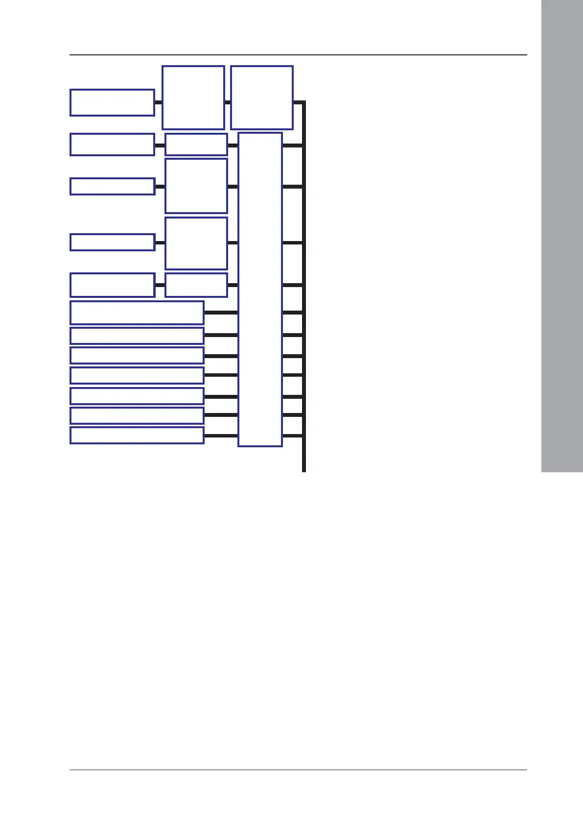
4.1.3 Output Event Statement
A simplified diagram showing valid outputs is
given below. More detail is given in
Section 4.3.2. The available outputs depend
upon the selected input (refer to panel
documentation for further information).
a. The output zone does not have to be the
same as the input zone. ‘Any Zone’ includes
the internal sounder circuits.
b. Available if ‘Zone’ is specified. Types are:
No restriction, Bell, Control. Sounders 3 and
4 can be configured in hardware as relay
outputs but are referred to as ‘Sounders’ in
the Control Matrix. Selecting ‘No restriction’
will drive sounders 1-4 even if 3 and 4 are set
as relays. Selecting ‘Bell’ will drive sounders
1 & 2, also 3 & 4 if they are configured as
sounders. Selecting ‘Control’ will drive 3 & 4
only if they are configured as relays.
c. Not applicable if input is ‘Disablement’,
‘Reset’, ‘Silence’ or ‘MCP in walk test’. Delay
also not available for Non-fire or TRUE inputs.
d. Used to: (i) transfer the output from one
Control Matrix entry to the input of another,
when both entries have a delay configured,
(ii) allow logic combinations (Section 4.1.5).
Up to 128 separate transfer flags can be used.
e. See Section 4.1.4.
f. These outputs are only available if the input
is NON-FIRE EVENT or TRUE.
g. These outputs are only available if the input
is NON-FIRE EVENT.
O
U
T
P
U
T
ID3000: MUTE BUZZER (g.)
ID2000: ACCEPT (g.)
SPECIFY
DEVICE,
ZONE(s) (a.),
VOP*, CELL(s)
OR SOUNDER
CIRCUIT
TYPE (b.),
STEADY/PULSE
(c.),
DELAY (c.),
TIME OF DAY
SELECT
SYSTEM &
ALARM OR
NON-FIRE
OPERATION (e.)
SPECIFY
DEVICE, VOP*,
ZONE(s), OR
SOUNDER
CIRCUIT
* = VIRTUAL OUTPUT POINT, see Section 1.5.11.
The Steady/Pulse option is replaced by mode 1 or 2.

 Loading...


