27Chapter 5 Mechanical Installation
Searchline Excel™ Plus / Searchline Excel™ Edge – Technical Manual
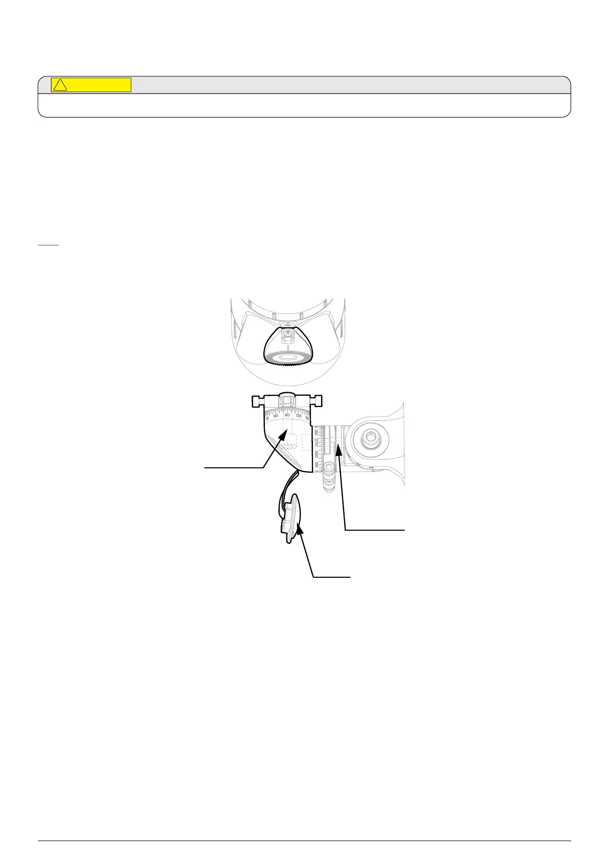
5.11Attach the instrument to the mount
Ensure the M6 Fine Adjustment Screws do NOT get in the way of cable glands.
1. Begin with the transmitter
2. Remove the bolt cover plate (Figure 10).
3. Attach the transmitter to the top spigot of the Universal Mounting Bracket.
4. Hold the instrument body to prevent from tilting during assembly and contact-tighten the spigot vertical M10 bolt.
5. At this stage, only contact-tighten the spigot horizontal M10 bolt.
Now repeat the same procedure with the receiver.
Note
The Adjustment Rings and M6 Fine Adjustment Screws will be set up later on during alignment.
Refer to Chapter 7 Alignment and Commissioning.
Spigot
vertical
M10 bolt
Bolt
cover
plate
Spigot
horizontal
M10 bolt
Figure 15.Attaching the instrument to the mount
 Loading...