33Chapter 6 Electrical Installation
Searchline Excel™ Plus / Searchline Excel™ Edge – Technical Manual
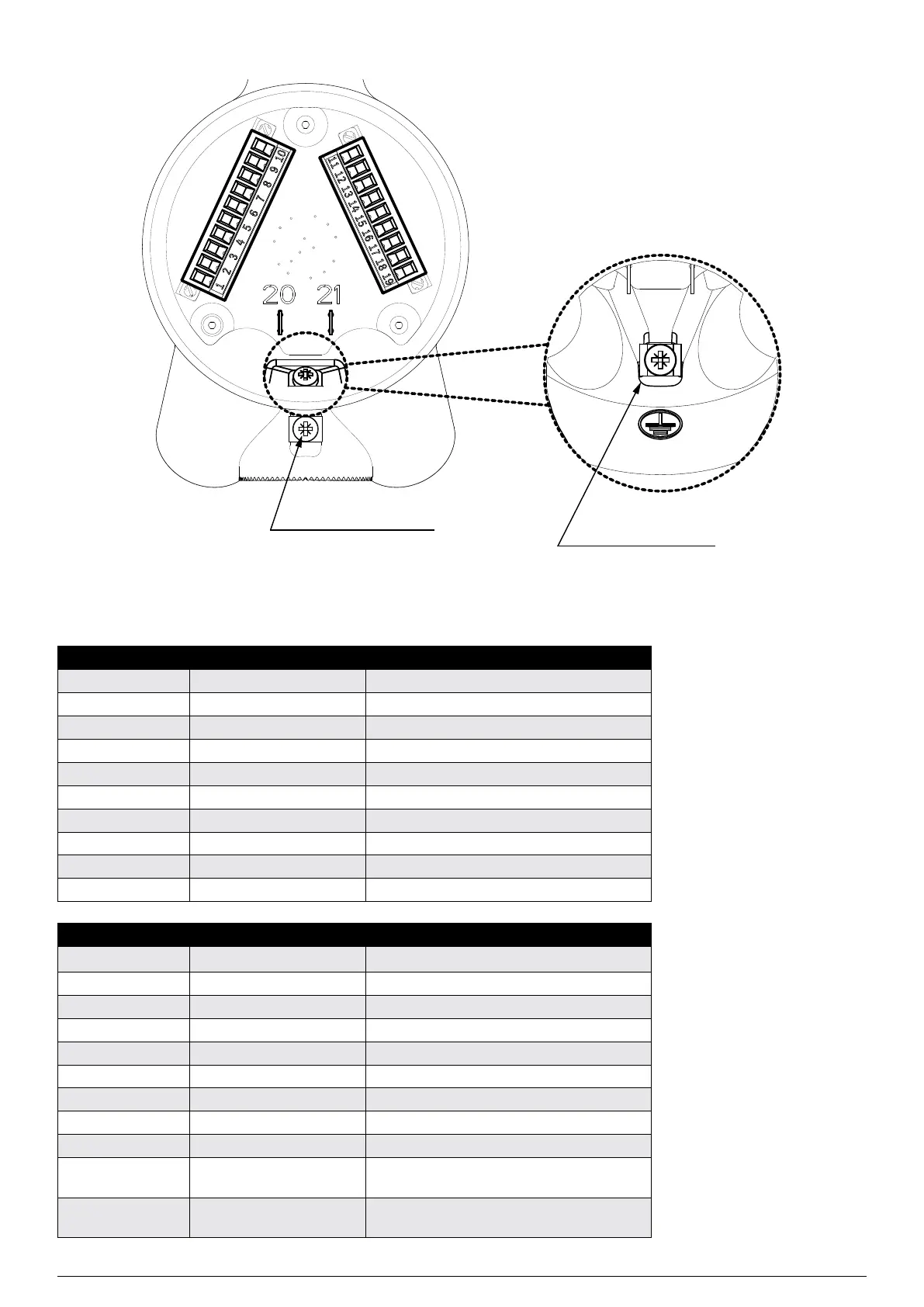
External earth connection
Internal earth connection
Figure 20.Receiver Terminal Wiring Compartment
6.2.1Receiver Terminal Wiring Description
Number Marking Description
1 RS485 A RS485 A (positive)
2 RS485 B RS485 B (negative)
3 RS485 D RS485 D (cable shielding)
4 RS485 D RS485 D (cable shielding)
5 420mA+ mA signal +
6 420mA mA signal -
7 24V DC Input power +
8 24V DC Input power +
9 0V DC Input power 0V
10 0V DC Input power 0V
Number Marking Description
11 Alarm 2 COM Alarm Relay 2 COM contact
12 Alarm 2 NC Alarm Relay 2 NC contact
13 Alarm 2 NO Alarm Relay 2 NO contact
14 Alarm 1 COM Alarm Relay 1 COM contact
15 Alarm 1 NC Alarm Relay 1 NC contact
16 Alarm 1 NO Alarm Relay 1 NO contact
17 Fault COM Fault Relay COM contact
18 Fault NC Fault Relay NC contact
19 Fault NO Fault Relay NO contact
20 HART+ HART handheld temporary connection
(positive)
21 HART HART handheld temporary connection
(negative)

 Loading...