28 Chapter 5 Mechanical Installation
Searchline Excel™ Plus / Searchline Excel™ Edge – Technical Manual
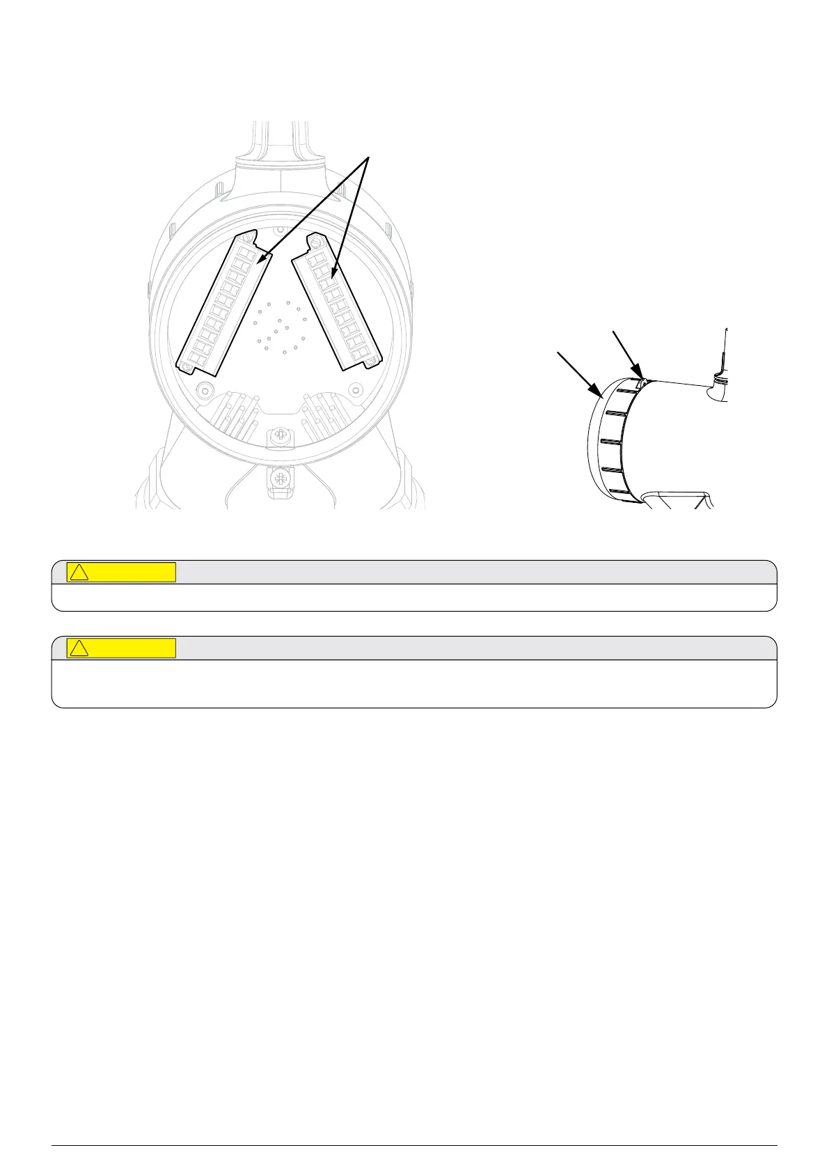
5.12Connect Wires to PCB Terminals
connectors
Wiring
Compartment
Cover
Figure 16.PCB Terminals
Remove power from the transmitter and receiver before performing any electrical installation or maintenance.
The equipment features pluggable connectors that are mechanically locked into position. These are not accessible by the
user during normal operation.
1. Loosen the grub screw enough to allow the wiring compartment cover to be unscrewed.
2. Unscrew the transmitter wiring compartment cover.
3. Unscrew and remove the pluggable connectors.
4. Connect wires as per local procedures. The connectors are clearly identified. Refer to the diagrams and tables shown in
Chapter 6 Electrical Installation of this manual for information on wiring.
5. Ensure that the O-rings on the transmitter body and in the wiring compartment cover are properly fitted and
not damaged.
6. Ensure that the threads of the wiring compartment cover are clean of dust.
7. Screw on the wiring compartment cover.
8. Tighten the grub screw to a final torque of 1.1 Nm (0.81 lb-ft)
9. Initially align the transmitter in the desired direction of the receiver by eye.
10. IMPORTANT: First, tighten the left-facing horizontal M10 bolt to final torque of 30 Nm (22 lb-ft).
11. IMPORTANT: Second, tighten the right-facing horizontal M10 bolt to final torque of 10 Nm (7.4 lb-ft).
12. Measure and record the distance (in metres) between the transmitter and receiver units. This distance is required later
in the alignment procedures.
At this point the transmitter and receiver will be positioned on their mountings so that their optical windows face each other:
 Loading...