38 Chapter 6 Electrical Installation
Searchline Excel™ Plus / Searchline Excel™ Edge – Technical Manual
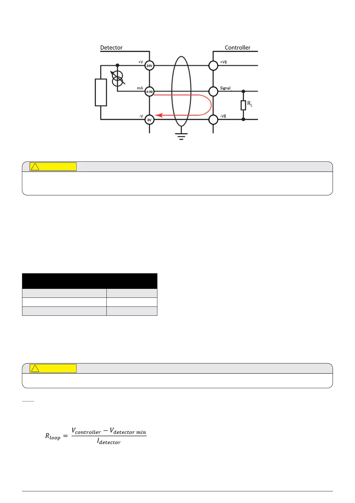
OELD Connection for mA Loop Configuration as Current Sink
Figure 27.mA loop configuration as current sink
The earth bonding arrangement must ensure that the maximum peak voltage between OELD case earth and any
field cable conductor is less than 350V. Voltages in excess of this can cause permanent damage to the OELD’s internal
RFI protection filters.
6.3Transmitter Electrical Installation
6.3.1Transmitter Power Supply Requirements
The transmitter requires a voltage supply of 1832 Vdc (nominal 24 Vdc). Peak current for transmitter is max. 0.7 A.
Inrush current for transmitters is 0.5 A for less than 20 ms.
Average (RMS) power consumption values:
Ambient Operating
Temperature
Power
consumption (W)
55°C (67°F) to 30°C (22°F) 11.8
30°C (22°F) to +30°C (+86°F) 5.6
above +30°C (+86°F) 3.8
Cold Start / Heat-up power consumption is max. 17 W. The heat-up period lasts approx. 20 min.
Ensure that the minimum required supply voltage 18 VDC is present at the transmitter, taking into account the voltage drop
due to cable resistance.
Temperature rating of the cable connected to the terminal must be suitable with respect to the installation environment.
Note
Make allowance for the insertion loss resistance.
The maximum loop resistance in the field cable is calculated as follows:
As an example, V
detector min
= 18 V; P
max
= 17 W; V
controller
will depend upon the connected power supply or control system.
Consult the manual of the given equipment for this information.
 Loading...