43Chapter 7 Alignment and Commissioning
Searchline Excel™ Plus / Searchline Excel™ Edge – Technical Manual
Do NOT adjust the aiming pattern using the Alignment Scope’s elevation and windage adjusters as they have been
factory set.
If the Alignment Scope is damaged or misaligned it must be returned to the factory for repair or realignment.
Keep the Alignment Scope and optics clean of dust to avoid scratches on the transmitter/receiver windows.
Notes
1. The Alignment Scope uses the same coaxial datum as used when the instrument was aligned in the factory to ensure
precise field alignment.
2. The Alignment Scope is specifically designed for simple and repeatable optimal alignment of the transmitter and
receiver and features a zoom function to enable efficient alignment.
7.4Basic Alignment
The basic procedure for aligning the transmitter and receiver is the same. The Searchline Excel Alignment Scope is used for
both Searchline Excel Plus & Searchline Excel Edge and is simply attached to the front face of the transmitter and receiver
(see Figure 34) and must be fitted to each of the instruments in turn, starting with the transmitter.
Ensure the transmitter and receiver face each other across the area. Follow the procedure described below.
Note:
Optical alignment may be carried out with power applied.
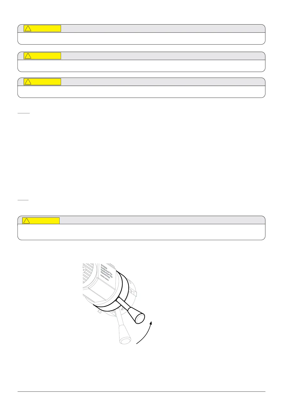
At start, ensure the Front lock handle is rotated counter-clockwise to its maximum and the Alignment Scope’s spacers are
precisely aligned with the instrument’s cowling gap before locking the fitting. Refer to Figure 32.
1. Ensure the Front lock handle is rotated counter-clockwise to its maximum (see Figure 32). This will pull the Alignment
Scope’s slots in.
Rotate front lock handle
counter-clockwise
to its maximum
Figure 32.Setting the initial position of Front lock handle
 Loading...