36 Chapter 6 Electrical Installation
Searchline Excel™ Plus / Searchline Excel™ Edge – Technical Manual
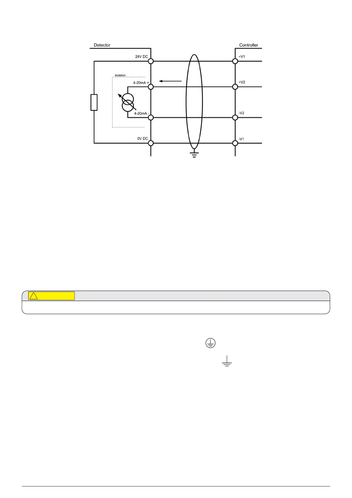
6.2.5Connection for mA Loop Configuration as Isolated Output
Figure 24.mA loop configuration as isolated output
6.2.6Cabling Recommendations
The cable used must be appropriate for the hazardous area classification and must meet local, national and company
regulations. The use of industrial grade, screened field cable is recommended.
An example may be a 3core copper cable with screen (minimum 90% coverage) and suitable mechanical protection
(e.g. steel wire armour) to suit an M25 or 3/4” NPT gland entry or conduit, suitable when mA loop and Modbus are used while
relay outputs are not utilized.
The allowable conductor size for the terminals is 0.25–2.5 mm² (24–12 AWG). The terminals will accept only wire sizes
(solid-core or stranded) in this range. The temperature rating of the conductors and cable glands should be greater than
80 °C (176 °F). The terminals should be torqued between 0.5 Nm to 0.6 Nm (0.3680.442 lb.ft).
Ensure that the cable gland is installed correctly and fully tightened. All unused cable/conduit entries must be sealed with
a suitable certified blanking plug. Use appropriate and certified cable glands, adapters and/or cable fittings to meet local
standards.
6.2.7Earthing Recommendations
Any earthing regime employed must avoid earth loops.
The following information is provided to assist with proper earthing of the transmitter and receiver:
• The transmitter and receiver have both INTERNAL and EXTERNAL earth points provided (see Electrical Connections).
This is to facilitate connection of the instrument to protective earth.
The INTERNAL earth point is marked with ground symbol in circle
It shall be used for the equipment grounding
connection. Internal earth must be at least equal in mm
2
to the incoming power conductors.
The EXTERNAL earth point is marked with ground symbol without circle
It provides a supplementary bonding
connection, which provides facility for connection of field wiring conductors of at least 4mm
2
.
• Field cable screens should be connected to instrument earth at the control room. The other end of the field cable
screen should be suitably terminated or isolated. It should not be connected to internal earth point.
6.2.8Modbus
Refer to Chapter 10 Communications of this manual for more information on Modbus.
 Loading...