330
GRE key disabled
Checksumming of GRE packets disabled
Output queue - Urgent queuing: Size/Length/Discards 0/100/0
Output queue - Protocol queuing: Size/Length/Discards 0/500/0
Output queue - FIFO queuing: Size/Length/Discards 0/75/0
Last clearing of counters: Never
Last 300 seconds input rate: 0 bytes/sec, 0 bits/sec, 0 packets/sec
Last 300 seconds output rate: 0 bytes/sec, 0 bits/sec, 0 packets/sec
Input: 0 packets, 0 bytes, 0 drops
Output: 0 packets, 0 bytes, 0 drops
# From Router B, ping the IP address of interface GigabitEthernet 2/0/1 on Router A.
[RouterB] ping -a 10.1.3.1 10.1.1.1
Ping 10.1.1.1 (10.1.1.1) from 10.1.3.1: 56 data bytes, press CTRL_C to break
56 bytes from 10.1.1.1: icmp_seq=0 ttl=255 time=2.000 ms
56 bytes from 10.1.1.1: icmp_seq=1 ttl=255 time=1.000 ms
56 bytes from 10.1.1.1: icmp_seq=2 ttl=255 time=1.000 ms
56 bytes from 10.1.1.1: icmp_seq=3 ttl=255 time=0.000 ms
56 bytes from 10.1.1.1: icmp_seq=4 ttl=255 time=1.000 ms
--- Ping statistics for 10.1.1.1 ---
5 packet(s) transmitted, 5 packet(s) received, 0.0% packet loss
round-trip min/avg/max/std-dev = 0.000/1.000/2.000/0.632 ms
The output shows that Router B can successfully ping Router A.
Troubleshooting GRE
The key to configuring GRE is to keep the configuration consistent. Most faults can be located by
using the debugging gre or debugging tunnel command. This section analyzes one type of fault
for illustration, with the scenario shown in Figure 139.
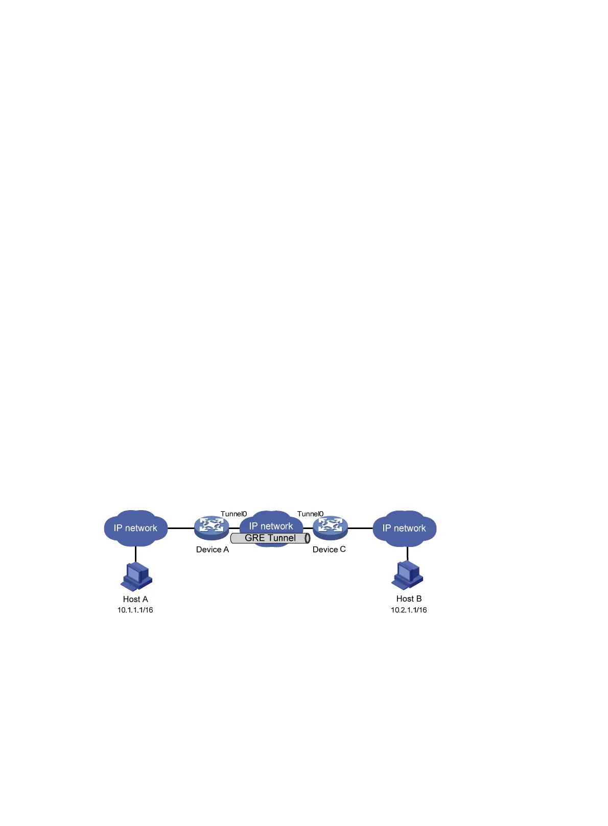
Figure 139
Network diagram
Symptom
The interfaces at both ends of the tunnel are configured correctly and can ping each other, but Host
A and Host B cannot ping each other.
Analysis
It might be because that Device A or Device C has no route to reach the peer network.
 Loading...


