60
[RouterA-dhcp-pool-2] dns-list 10.1.1.2
[RouterA-dhcp-pool-2] gateway-list 10.1.1.254
Verifying the configuration
# Verify that clients on subnets 10.1.1.0/25 and 10.1.1.128/25 can obtain correct IP addresses and
all other network parameters from Router A. (Details not shown.)
# On the DHCP server, display the IP addresses assigned to the clients.
[RouterA] display dhcp server ip-in-use
DHCP user class configuration example
Network requirements
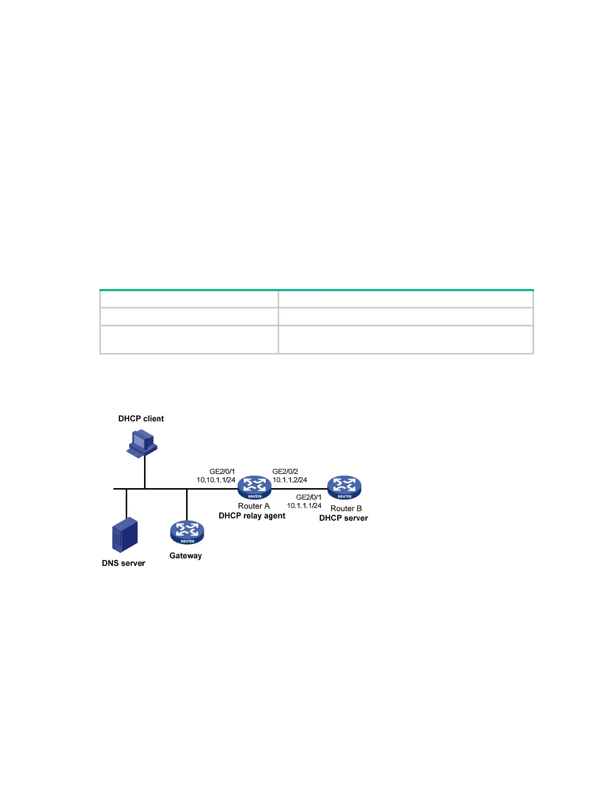
As shown in Figure 26, the DHCP relay agent (Router A) forwards DHCP packets between DHCP
clients and the DHCP server (Router B). Enable Router A to handle Option 82 so that it can add
Option 82 in DHCP requests and then convey them to the DHCP server.
Configure the address allocation scheme as follows:
Assign IP addresses To clients
10.10.1.2 to 10.10.1.10 The DHCP request contains Option 82.
10.10.1.11 to 10.10.1.26
The hardware address in the request is six bytes long and
begins with
aabb-aabb-aab
.
Router B assigns the DNS server address 10.10.1.20/24 and the gateway address 10.10.1.254/24 to
clients on subnet 10.10.1.0/24.
Figure 26 Network diagram
Configuration procedure
1. Specify IP addresses for the interfaces on DHCP server. (Details not shown.)
2. Configure DHCP:
# Enable DHCP and configure the DHCP server to handle Option 82.
<RouterB> system-view
[RouterB] dhcp enable
[RouterB] dhcp server relay information enable
# Enable the DHCP server on the interface GigabitEthernet 2/0/1.
[RouterB] interface gigabitethernet 2/0/1
[RouterB-GigabitEthernet2/0/1] dhcp select server
 Loading...


