63
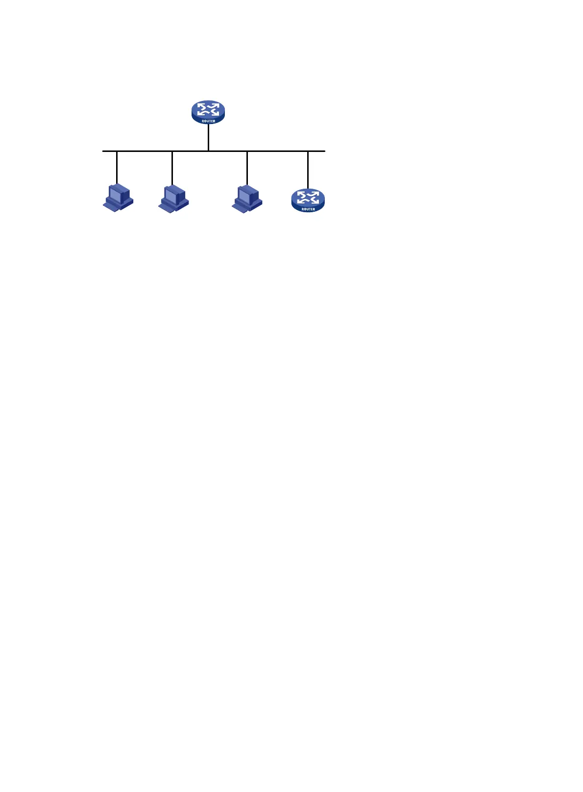
Figure 28 Network diagram
Configuration procedure
# Enable DHCP.
<RouterA> system-view
[RouterA] dhcp enable
# Configure the primary and secondary IP addresses of interface GigabitEthernet 2/0/1, and enable
the DHCP server on GigabitEthernet 2/0/1.
[RouterA] interface gigabitethernet 2/0/1
[RouterA-GigabitEthernet2/0/1] ip address 10.1.1.1 24
[RouterA-GigabitEthernet2/0/1] ip address 10.1.2.1 24 sub
[RouterA-GigabitEthernet2/0/1] dhcp select server
[RouterA-GigabitEthernet2/0/1] quit
# Create DHCP address pool aa.
[RouterA] dhcp server ip-pool aa
# Specify the primary subnet and the gateway for dynamic allocation.
[RouterA-dhcp-pool-aa] network 10.1.1.0 mask 255.255.255.0
[RouterA-dhcp-pool-aa] gateway-list 10.1.1.254
# Specify the secondary subnet and the gateway for dynamic allocation.
[RouterA-dhcp-pool-aa] network 10.1.2.0 mask 255.255.255.0 secondary
[RouterA-dhcp-pool-aa-secondary] gateway-list 10.1.2.254
[RouterA-dhcp-pool-aa-secondary] quit
[RouterA-dhcp-pool-aa]
Verifying the configuration
# Verify that the DHCP server assigns clients IP addresses and gateway address from the secondary
subnet when no assignable address is available from the primary subnet. (Details not shown.)
# On the DHCP server, display IP addresses assigned to the clients.
[RouterA] display dhcp server ip-in-use
DHCP option customization configuration example
Network requirements
As shown in Figure 29, DHCP clients obtain IP addresses and PXE server addresses from the DHCP
server (Router A). The subnet for address allocation is 10.1.1.0/24.
...
GatewayDHCP client DHCP client DHCP client
Router A
DHCP server
GE2/0/1
10.1.1.1/24
10.1.2.1/24 sub

 Loading...


