262
Static route configuration example
Network requirements
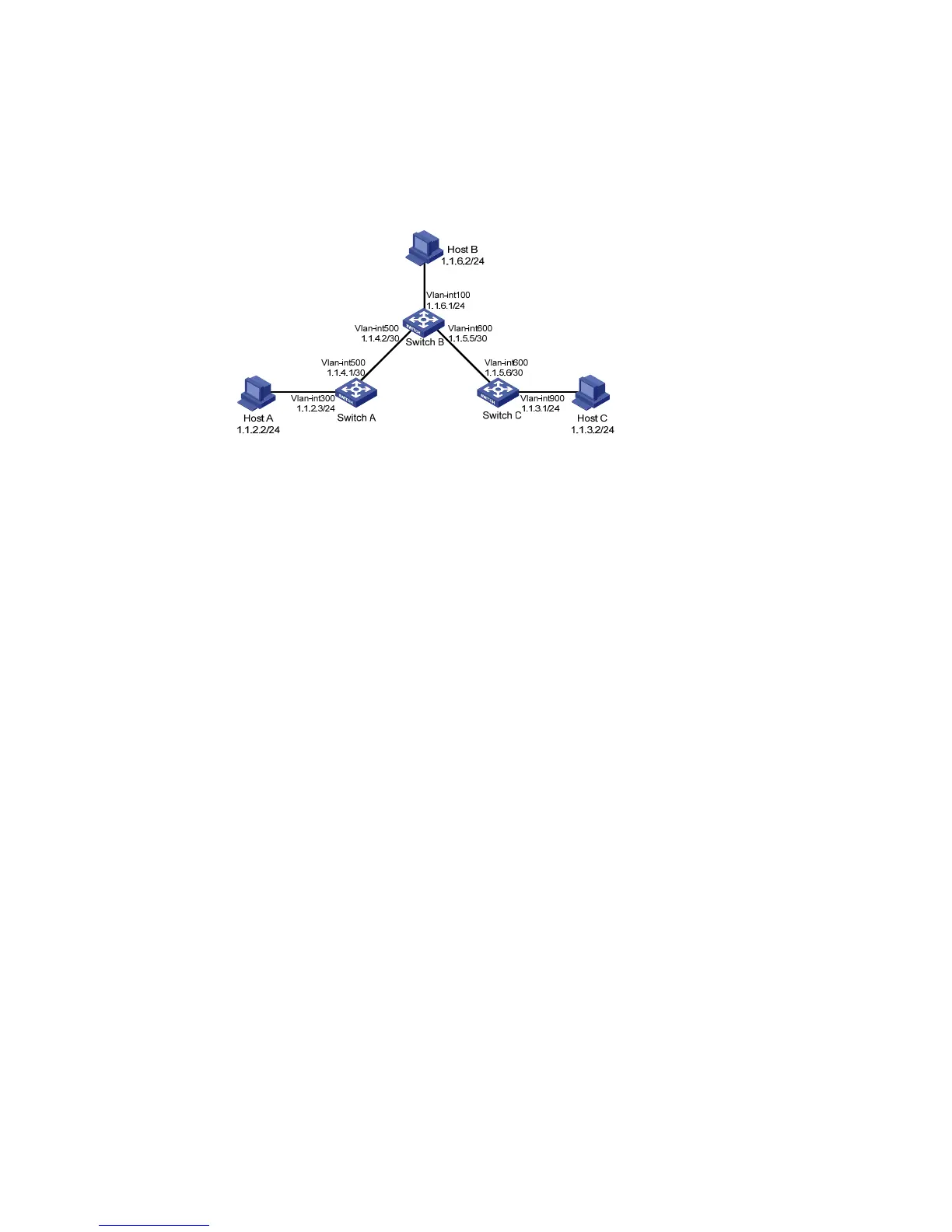
The IP addresses of devices are shown in Figure 228. Configure IPv4 static routes on Switch A, Switch B,
and Switch C so that any two hosts can communicate with each other.
Figure 228 Network diagram for IPv4 static route configuration
Configuration outlines
1. On Switch A, configure a default route with Switch B as the next hop.
2. On Switch B, configure one static route with Switch A as the next hop and the other with Switch C
as the next hop.
3. On Switch C, configure a default route with Switch B as the next hop.
Configuration procedure
1. Configure the IP addresses of the interfaces (omitted)
2. Configure IPv4 static routes
# Configure a default route to Switch B on Switch A.
Select Network > IPv4 Routing from the navigation tree of Switch A, and then click the Create tab
to enter the page shown in Figure 229.
Type 0.0.0.0 for Destination IP Address.
Select 0 (0.0.0.0) from the Mask drop-down list.
Type 1.1.4.2 for Next Hop.
Click Apply.