449
NOTE:
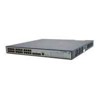
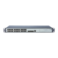
HP V1910-24G-PoE (365W) Switch JE007A and HP V1910-24G-PoE (170W) Switch JE008A are
devices with a single PSE, so this document describes the device with a single PSE only.
A PSE can examine the Ethernet cables connected to PoE interfaces, search for PDs, classify them, and
supply power to them. When detecting that a PD is unplugged, the PSE stops supplying power to the PD.
PI
An Ethernet interface with the PoE capability is called PoE interface. A PoE interface can be an FE or GE
interface.
The PSE supplies power for a PoE interface in the following two modes:
Over signal wires—The PSE uses the pairs (1, 2, 3, 6) for transmitting data in a category 3/5
twisted pair cable to supply DC power while transmitting data to PDs.
Over spare wires—The PSE uses the pairs (4, 5, 7, 8) not transmitting data in a category 3/5
twisted pair cable to supply DC power to PDs.
NOTE:
HP V1910-24G-PoE (365W) Switch JE007A and HP V1910-24G-PoE (170W) Switch JE008A only
support the signal mode.
PD
A PD is a device accepting power from the PSE, including IP phones, wireless APs, chargers of portable
devices, POS, and web cameras.
The PD that is being powered by the PSE can be connected to another power supply unit for redundancy
power backup.
Protocol specification
The protocol specification related to PoE is IEEE 802.3af.
Configuring PoE
CAUTION:
Before configuring PoE, make sure that the PoE power supply and PSE are operating properly; otherwise,
you cannot configure PoE or the configured PoE function does not take effect.
Configuring PoE ports
Select PoE > PoE from the navigation tree and click the Port Setup tab, as shown in Figure 424.
 Loading...
