OperatiOn
HPR800XD Auto Gas – 806500 4-19
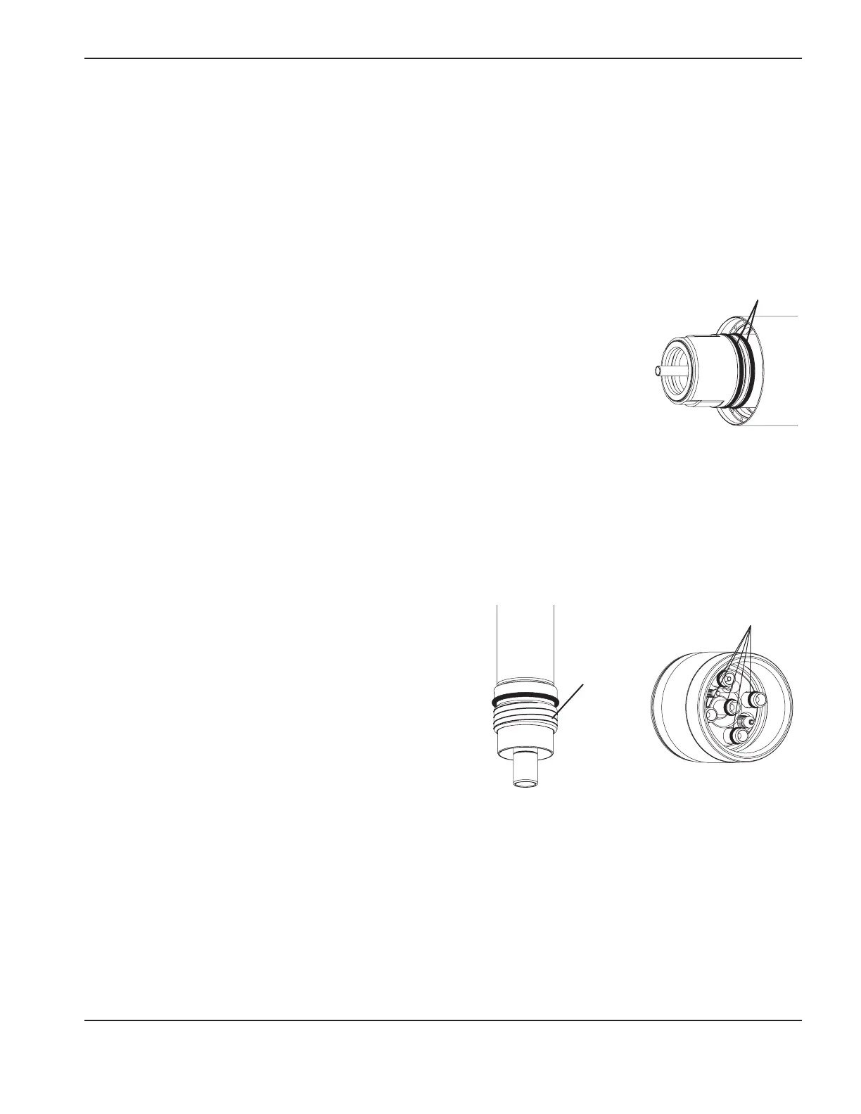
Torch maintenance
Poor cut quality and premature failure may occur if the HPR torch is not maintained properly.
The torch is manufactured to very tight tolerances to maximize cut quality. The torch should not be subjected to hard
impacts that can cause critical features to become misaligned.
The torch should be stored in a clean location when not in use, to avoid contamination of critical surfaces and passages.
Routine maintenance
The following steps should be completed each time consumables are changed:
1. Use a clean cloth to wipe off the torch inside and outside. A cotton swab can be
used to access hard-to-reach internal surfaces.
2. Use compressed air to blow away any remaining dirt and debris from internal
andexternal surfaces.
3. Apply a thin film of silicone lubricant on each external o-ring. The o-rings should
look shiny, but there should not be any excess or built-up grease.
4. If consumables will be reused, use a clean cloth to wipe them off, and use
compressed air to blow them off before they are installed again. This is especially
critical for the nozzle retaining cap.
Quick-disconnect maintenance
The following steps should be completed every 5-10 times
consumables are changed:
1. Remove the torch from the quick-disconnect assembly.
2. Use compressed air to blow off all internal surfaces and
the external threads.
3. Use compressed air to blow off all internal surfaces at the
rear of the torch.
4. Inspect each of the 5 o-rings at the rear of the torch for
nicks or cuts. Replace any damaged o-rings. If they are
not damaged, apply a thin film of silicone lubricant on each
o-ring. The o-rings should look shiny, but there should not
be any excess or built-up grease.
Maintenance kit
Even with proper care, the o-rings at the rear of the torch will need to be replaced periodically. Hypertherm provides a
kit (128879) of replacement parts. The kit contains o-rings, a seal, and 2 water tubes. Kits should be kept in stock and
be used as part of your routine maintenance schedule.
External
o-rings (2)
External
threads
Rear view of the torch
O-rings (5)
Front view of the torch