Troubleshoot Common Problems
156 810470 Operator Manual Powermax65/85/105 SYNC
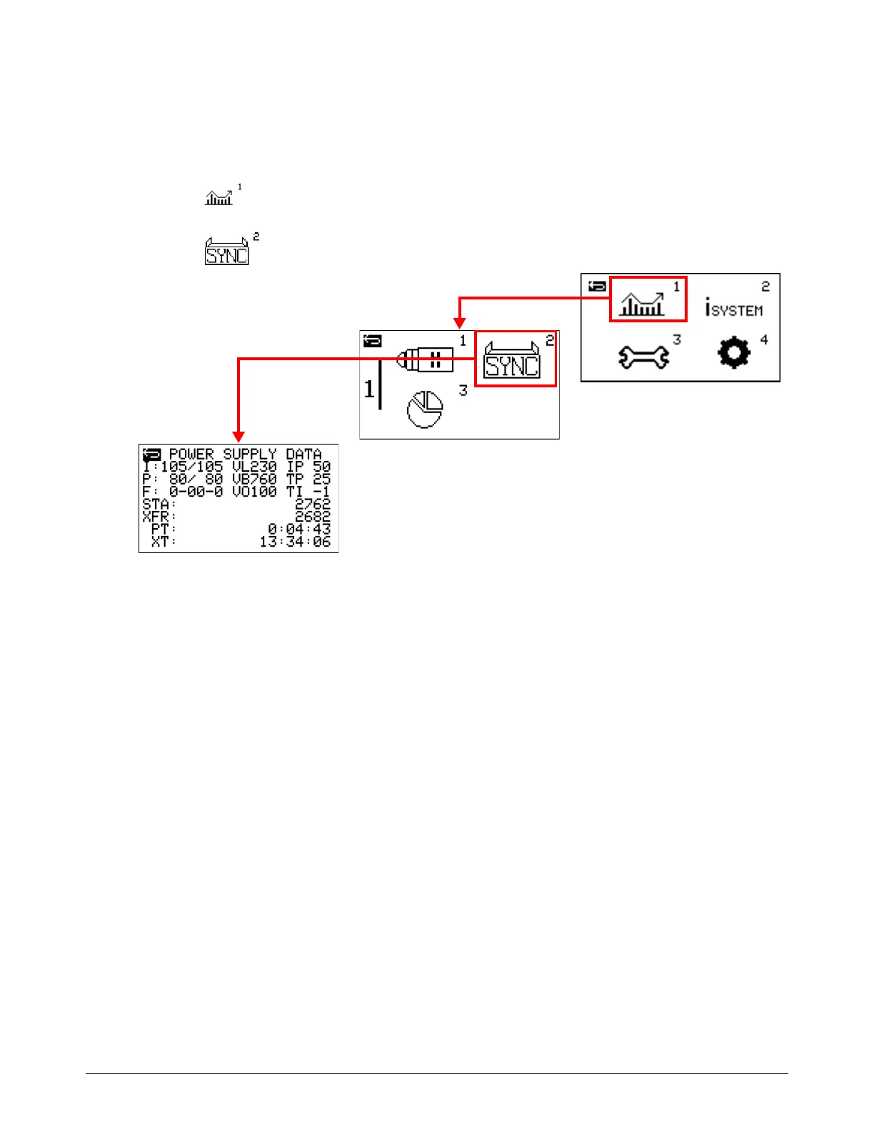
Power Supply Data screen
Go to the Power Supply Data screen (POWER SUPPLY DATA) to see information about plasma
power supply performance and use.
1. Select on the main menu screen.
2. Select to go to the POWER SUPPLY DATA screen.
I – This field shows the set current followed by the live output current (in amperage).
P – This field shows the inlet set pressure followed by the actual output gas pressure (in psi).
F – This field shows the active fault code (if any).
VL – This field shows the input voltage.
VB – This field shows the bus voltage (VBUS).
VO – This field shows the arc voltage.
IP – This field shows the boost PFC IGBT current in amperage. This field shows on the screen for
CSA and for Powermax105 SYNC 230 V – 400 V CE models only.
TP – This field shows the boost PFC IGBT temperature in Celsius. This field shows on the screen
for CSA and for Powermax105 SYNC 230 V – 400 V CE models only.
TI – This field shows the inverter IGBT temperature in Celsius.
STA – This field shows the total number of torch starts the plasma power supply has done in its life.
 Loading...