VESA Video Feature Connector
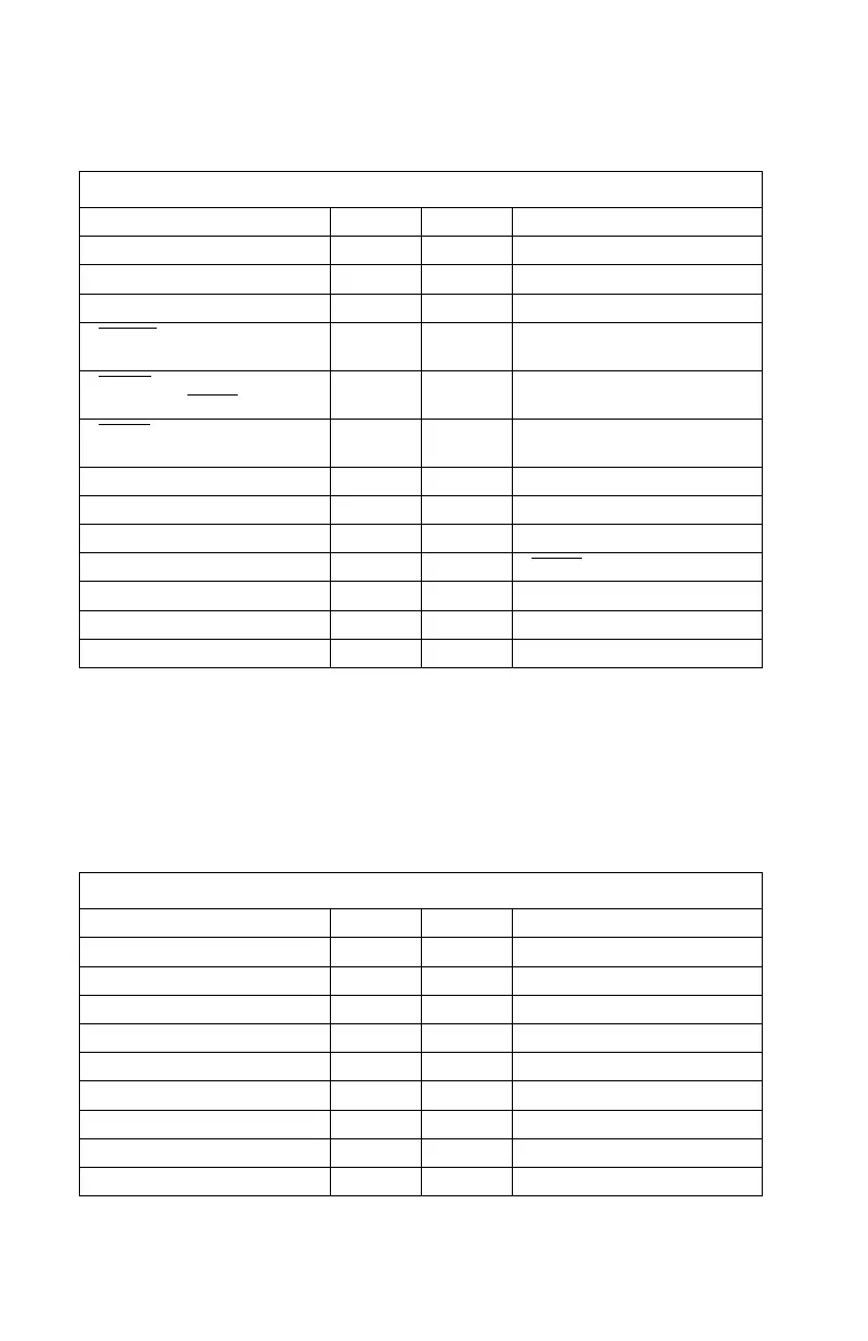
Table 5-5. VESA Video Feature Connector
Description Pin Pin Description
Ground 1 2 Pixel Data(0)
Ground 3 4 Pixel Data(1)
Ground 5 6 Pixel Data(2)
EVIDEO
: External pixel data
enable
7 8 Pixel Data(3)
ESYNC
: External HSYNC,
VSYNC and
BLANK
enable
9 10 Pixel Data(4)
EDCLK
: External Dot Clock
enable
11 12 Pixel Data(5)
No Connection 13 14 Pixel Data(6)
Ground 15 16 Pixel Data(7)
Ground 17 18 DCLK: Dot Clock
Ground 19 20
BLANK
Ground 21 22 HSYNC
No Connection 23 24 VSYNC
No Connection 25 26 Ground
VESA Local Bus Riser Connector
The signals marked (PCI RISER) are present to support the PCI riser card.
They are not used with VESA local bus or ISA-only risers. The VESA
connector on the VESA riser has a plastic divider in those positions.
Table 5-6 (Page 1 of 3). VESA Local Bus Riser Connector
Description Pin Pin Description
CD(0) B01 A01 CD(1)
CD(2) B02 A02 CD(3)
CD(4) B03 A03 Ground
CD(6) B04 A04 CD(5)
CD(8) B05 A05 CD(7)
Ground B06 A06 CD(9)
CD(10) B07 A07 CD(11)
CD(12) B08 A08 CD(13)
VCC B09 A09 CD(15)
5-28
 Loading...


