5: S
PECIAL
F
UNCTIONS
5-34 S
MART
AXIS P
RO
/L
ITE
U
SER
'
S
M
ANUAL
FT9Y-B1378
Interrupt Input
When a quick response to an external input is required, such as positioning control, the interrupt input can call a subroutine to
execute an interrupt program. The interrupt input can only be used when ladder program is selected as the programming
language.
Six inputs I0, I2, I3, and I5 through I7 can be designated to execute interrupt at a rising and/or falling edge of input pulses. When
an interrupt is initiated by inputs I0, I2, I3, and I5 through I7, program execution immediately jumps to a predetermined label
number stored in special data registers D8032 through D8035, D8037, and D8038 respectively. The Function Area Settings dialog
box is used to designate inputs I0, I2, I3, and I5 through I7 as an interrupt input, normal input, high-speed counter input, or catch
input.
Normal input signals to input terminals are read when the END instruction is executed at the end of a scan.
Since these settings relate to the user program, the user program must be downloaded to the SmartAXIS after changing any of
these settings.
Interrupt Input Terminals, Special Data Registers, and Special Internal Relays for Interrupt Inputs
Note: Only the 24-, 40-, and 48-I/O types can use external inputs I6 and I7 as interrupt inputs. The 12-I/O type cannot use external inputs I6 and
I7 as interrupt inputs.
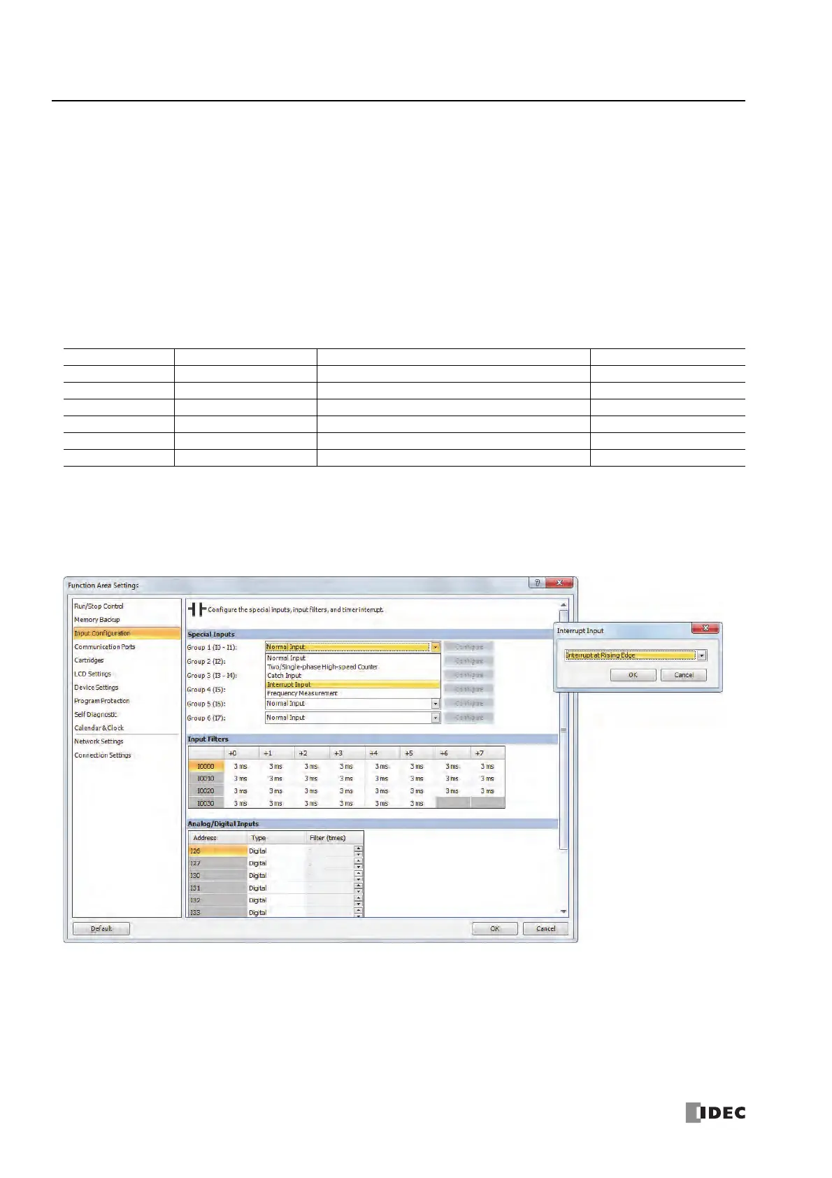
Programming WindLDR
1. From the WindLDR menu bar, select Configuration > Input Configuration.
The Function Area Settings dialog box for Input Configuration appears.
2. Select Interrupt Input in the Groups 1 through 6 pull-down list boxes. the Interrupt Input dialog box appears.
3. Select an interrupt edge in the pull-down list for each group.
Disable and Enable Interrupts
The interrupt inputs I0, I2, I3, and I5 through I7 and timer interrupt are normally enabled while the SmartAXIS is running, and can
also be individually disabled using the DI instruction or enabled using the EI instruction. When interrupt inputs I0, I2, I3, and I5
through I7 are enabled, special internal relay M8070 through M8075 are turned on, respectively. See Chapter 16 "Interrupt Control
Instructions" in the "SmartAXIS Ladder Programming Manual".
Group Interrupt Input No. Interrupt Input Jump Destination Label No. Interrupt Input Status
Group 1 I0 D8032 M8070
Group 2 I2 D8033 M8071
Group 3 I3 D8034 M8072
Group 4 I5 D8035 M8073
Group 5 I6 D8037 M8074
Group 6 I7 D8038 M8075
Interrupt Input Rising/
Falling Edge Selection
Interrupt at Rising Edge
Interrupt occurs when the
interrupt input turns on.
Interrupt at Falling Edge
Interrupt occurs when the
interrupt input turns off.
Interrupt at Both Edges
Interrupt occurs when the
interrupt input turns on or off.

 Loading...

