S
MART
AXIS P
RO
/L
ITE
U
SER
'
S
M
ANUAL
FT9Y-B1378 10-1
10:USER COMMUNICATION INSTRUCTIONS
Introduction
This chapter describes user communication that converts the specified data to the data type for the external devices connected to
the SmartAXIS and sends and receives that data.
User communication allows the following two types of communication methods:
• Serial communication with an external device connected to the RS232C port or the RS485 port
• Ethernet communication with an external device connected by the Ethernet port
User Communication via Serial Communication
This section describes the user communication function for communication between the SmartAXIS and external devices with an
RS232C or RS485 port, such as a computer, modem, printer, or barcode reader. The SmartAXIS uses user communication
instructions for transmitting and receiving communication to and from external devices.
User Communication Overview
By installing a communication cartridge on the SmartAXIS expansion communication port, the SmartAXIS can communicate with
two external devices simultaneously.
When using an RS485 communication cartridge, SmartAXIS modules can communicate with a maximum of 31 RS485 devices
using the user communication.
User communication transmit and receive instructions can be programmed to match the communication protocol of the equipment
to communicate with. Possibility of communication using the user communication mode can be determined referring to the user
communication mode specifications described below.
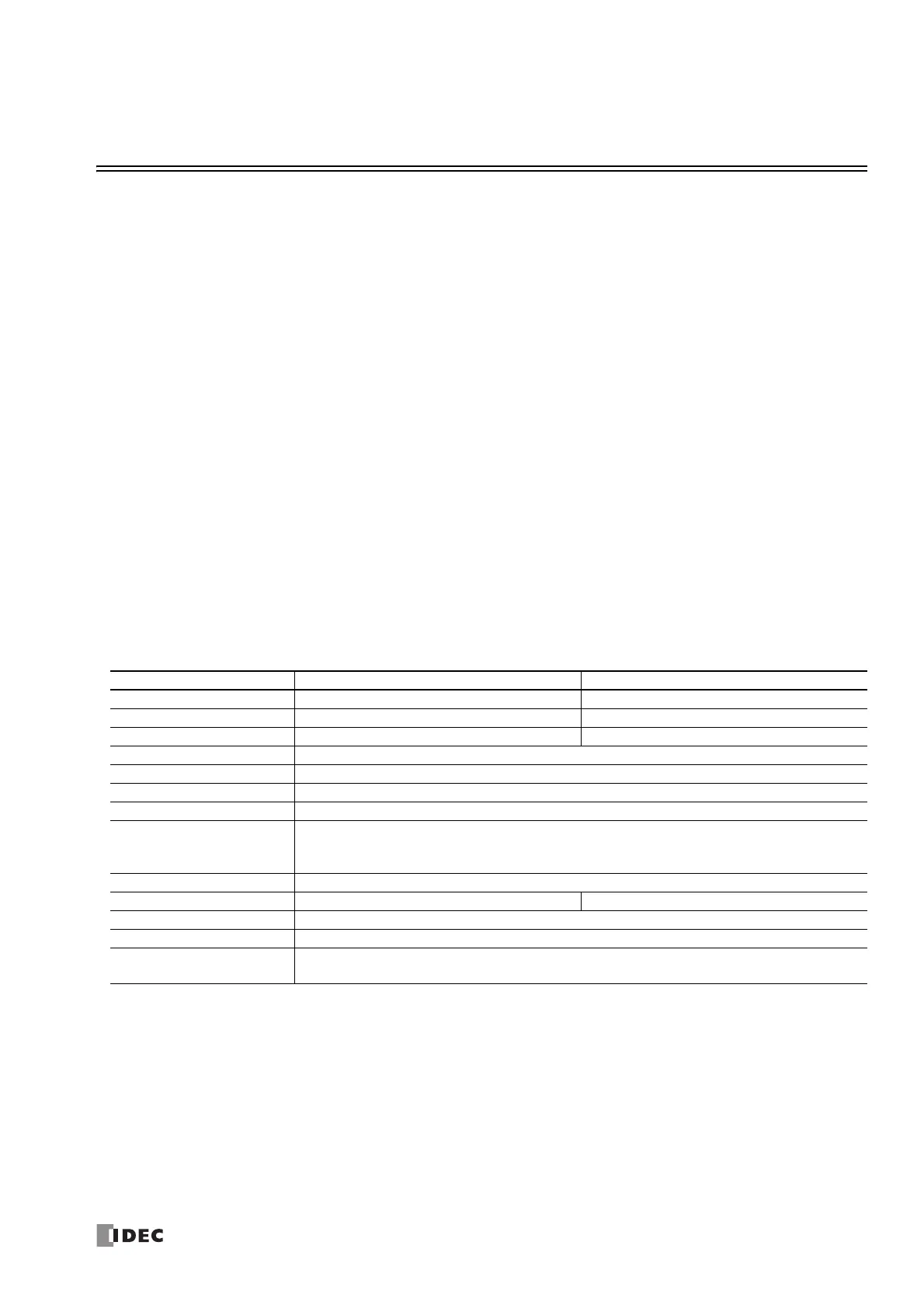
User Communication Mode Specifications
Note: The following configuration cannot be selected: Data Bits: 7, Parity: None
Type RS232C User Communication RS485 User Communication
Communication Port Port 2 and Port 3 Port 2 and Port 3
Maximum Nodes 1 per port 31 maximum
Standards EIA RS232C EIA RS485
Baud Rate 1200, 2400, 4800, 9600, 19200, 38400, 57600, 115200 bps (Default: 115200)
Data Bits 7 or 8 bits (Default: 7) (Note)
Parity Odd, Even, None (Default: Even) (Note)
Stop Bits 1 or 2 bits (Default: 1)
Receive Timeout
10 to 2540ms (10ms increments) or none
(Receive timeout is disabled when 2550 ms is selected.)
The receive timeout has an effect when using RXD instructions.
Communication Method Start-stop synchronization system
Maximum Cable Length 3m 200m
Maximum Transmit Data 200 bytes
Maximum Receive Data 200 bytes
BCC Calculation
XOR, ADD, ADD-2comp *, Modbus ASCII *, Modbus RTU *
(* For calculation examples, see "BCC Calculation Examples" on page 10-28.)

 Loading...

