S
MART
AXIS P
RO
/L
ITE
U
SER
'
S
M
ANUAL
FT9Y-B1378 8-9
8: I
NSTRUCTIONS
/F
UNCTION
B
LOCKS
R
EFERENCE
FB List
This section lists the SmartAXIS FBs and describes their functions. For details, see the "SmartAXIS FBD Programming Manual".
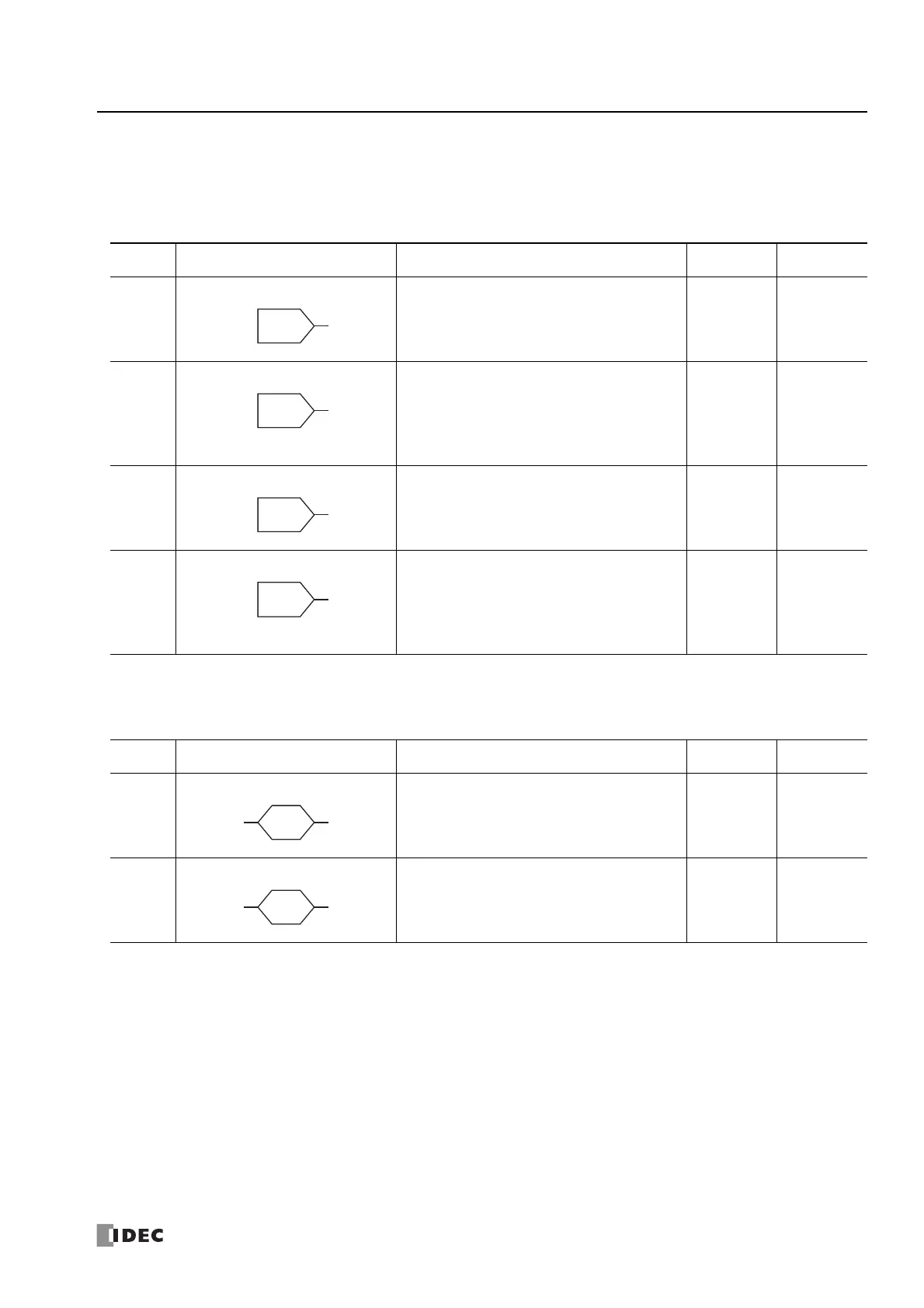
Input FB
This section describes the input FB of the SmartAXIS and its functions.
Output FB
This section describes the output FB of the SmartAXIS and its functions.
Symbol Name and Diagram Function
Output
inversion
FBD manual
page
I
Digital Input
Inputs ON/OFF information from an external device
to the SmartAXIS.
–5-1
M
Special Internal Relay Special internal relays can be used as bit inputs for
function blocks. Special function is allocated to each
special internal relay.
For details on the individual special internal relays,
see Chapter 7 "Device Addresses" - "Special Internal
Relays" on page 7-2.
–5-2
R
Shift Register
Outputs ON/OFF state of a shift register device. – 5-3
AI
Analog Input The analog input values (0 to 10V DC) for the analog
input terminals are converted to digital values (0 to
1,000) and output. With the analog input linear
transformation function, the analog input value can
be linearly transformed within a range of -32,768 to
32,767.
–5-4
Symbol Name and Diagram Function
Output
inversion
FBD manual
page
Q
Digital Output
Outputs ON/OFF information from the SmartAXIS to
an external device.
–6-1
M
Internal Relay
A bit unit function block used internally by the
SmartAXIS.
–6-2

 Loading...

