S
MART
AXIS P
RO
/L
ITE
U
SER
'
S
M
ANUAL
FT9Y-B1378 5-73
5: S
PECIAL
F
UNCTIONS
Connection Settings
This section describes the configurations of the SmartAXIS module for client/server connections..
Applications
The SmartAXIS supports Ethernet communication functions with a maximum of three connections. Using those connections,
maintenance communication, Modbus TCP communication, user communication, and remote I/O communication can be used.
Those communications can be configured in the Function Area Settings dialog box.
Description of functions
The SmartAXIS has a maximum of three connections for the maintenance communication server, user communication server,
Modbus TCP communication server, user communication client, Modbus TCP communication client and remote I/O master.
To limit the access to the SmartAXIS, IP address flittering can be used. By specifying the IP address that can access the
SmartAXIS, anonymous access can be prevented.
Connection Status and Connected IP Address
The connection status of connections with remote hosts can be confirmed with special internal relays M8110 to M8112. When a
connection with a remote host is established, the corresponding special internal relay is turned on. When the connection is
disconnected, the corresponding special internal relay is turned off. The IP addresses of the remote hosts can be confirmed with
special data registers D8110 to D8121.
Note: R/W is the abbreviation for read/write. When R/W, it can be read and written. When R, it can only be read. When W, it can only be written.
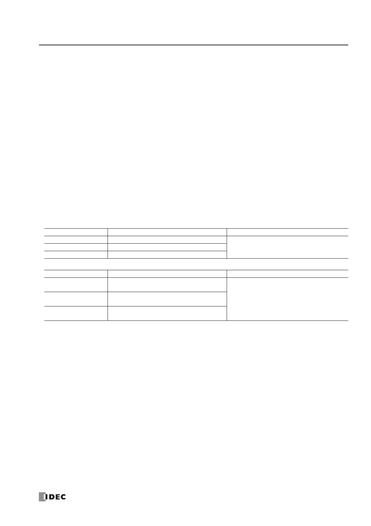
Special Internal Relays
Special Data Registers
Device Address Description Details
M8110 Connection 1 Status
While a connection is established with a remote host,
the special internal relay will be on. When no
connection is established, it will be off.
M8111 Connection 2 Status
M8112 Connection 3 Status
Device Address Description Details
D8110-D8113
Connection 1
Connected IP Address
IP address is stored in the corresponding special data
registers. For example, when the IP address is
aaa.bbb.ccc.ddd, each value is stored as follows:
D8110=aaa, D8111=bbb, D8112=ccc, and
D8113=ddd.
D8114-D8117
Connection 2
Connected IP Address
D8118-D8121
Connection 3
Connected IP Address

 Loading...

