S
MART
AXIS P
RO
/L
ITE
U
SER
'
S
M
ANUAL
FT9Y-B1378 4-11
4: O
PERATION
B
ASICS
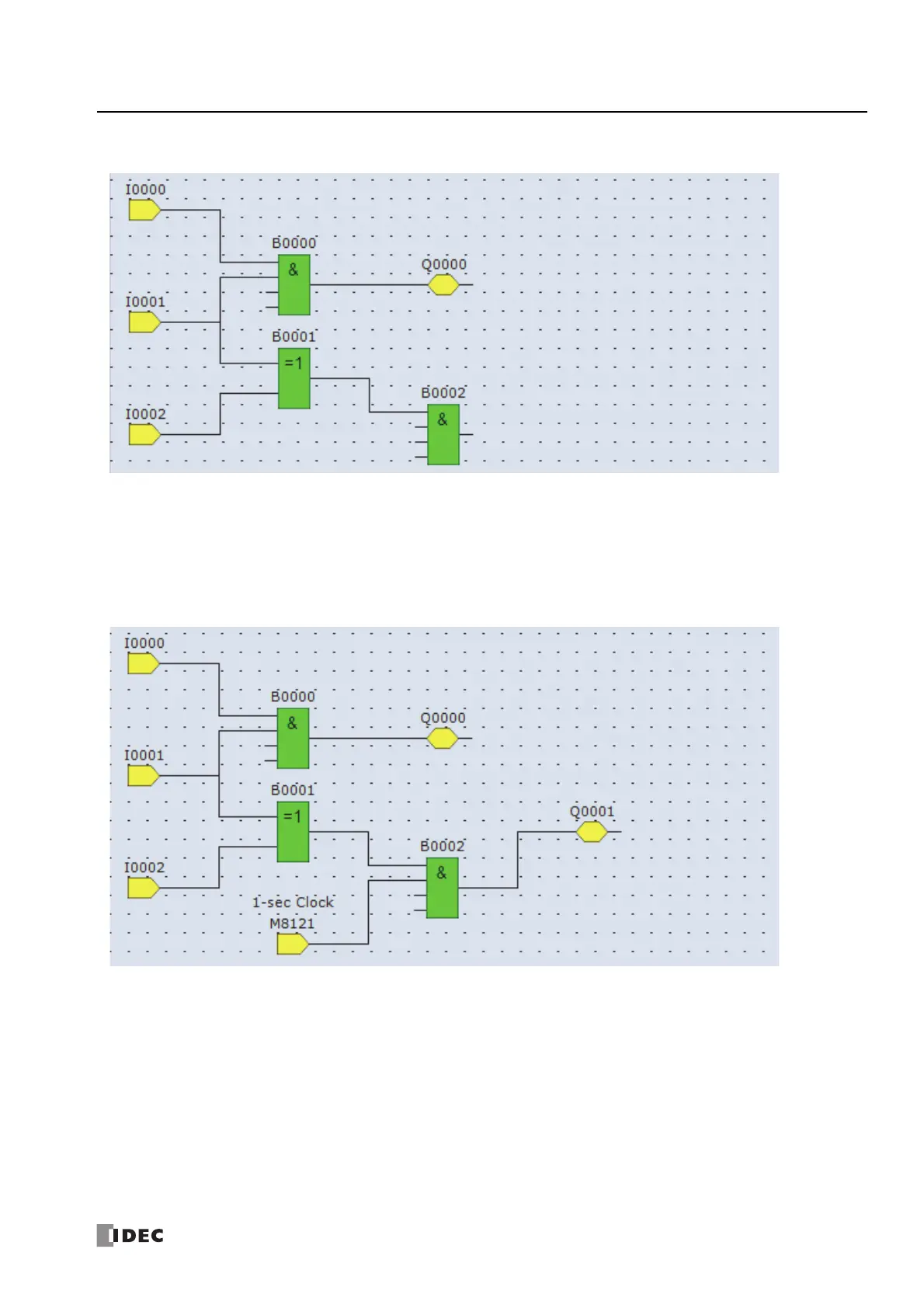
Insert input I2 and XOR B1. Connect input I1 and I2 to the inputs 1 and 2 of XOR B1.
The output connector of the FB can be connected to multiple FB input connectors. Multiple output connectors of FBs cannot be
connected to a single input connector of an FB.
Insert special internal relay M8121, AND B2, and output Q1 and connect them.
Note: M8121 is a special internal relay that continuously turns on and off in a one second cycle. For details on the special internal relay, see "Special
Internal Relay Device Addresses" on page 7-2.
Creating the sample FBD program is now complete.
Convert Program
The program can be checked whether it contains any user program syntax error.
From the menu bar, select Home > Convert (Program group).
When the instruction/FB symbols are connected correctly, the program conversion is completed successfully. If any error is found,
the errors are listed on the Info Window. Then, make corrections as necessary.
Save Project
1. Select the WindLDR application button at the upper-left corner of the WindLDR screen, followed by Save, and type TEST01 in
the File Name field. Change the Folder or Drive as necessary.

 Loading...

