11: M
ODBUS
C
OMMUNICATION
11-12 S
MART
AXIS P
RO
/L
ITE
U
SER
'
S
M
ANUAL
FT9Y-B1378
Communication Format
This section describes the communication format for each function code from the slave number up to immediately before the
check code.
Function Code 01 (Read Coil Status) and Function Code 02 (Read Input Status)
Function code 01 reads bit device statuses of Q (output), R (shift register), or M (internal relay). One through 128 consecutive bits
can be read out.
Function code 02 reads bit device statuses of I (input), T (timer contact), or C (counter contact). One through 128 consecutive bits
can be read out.
Communication Frame
Request from Modbus Master
ACK Reply from Modbus Slave
NAK Reply from Modbus Slave
Communication Example
• RTU Mode
Purpose
Read 15 bits starting at output Q10.
Q10 → (1 – 0) × 8 + 0 + 1 = 9
Modbus address: 9
9 – 1 = 8 = 8h
Communication frame address: 0008h
Condition
Slave No. 8
Q10 through Q27 binary data: 1234h
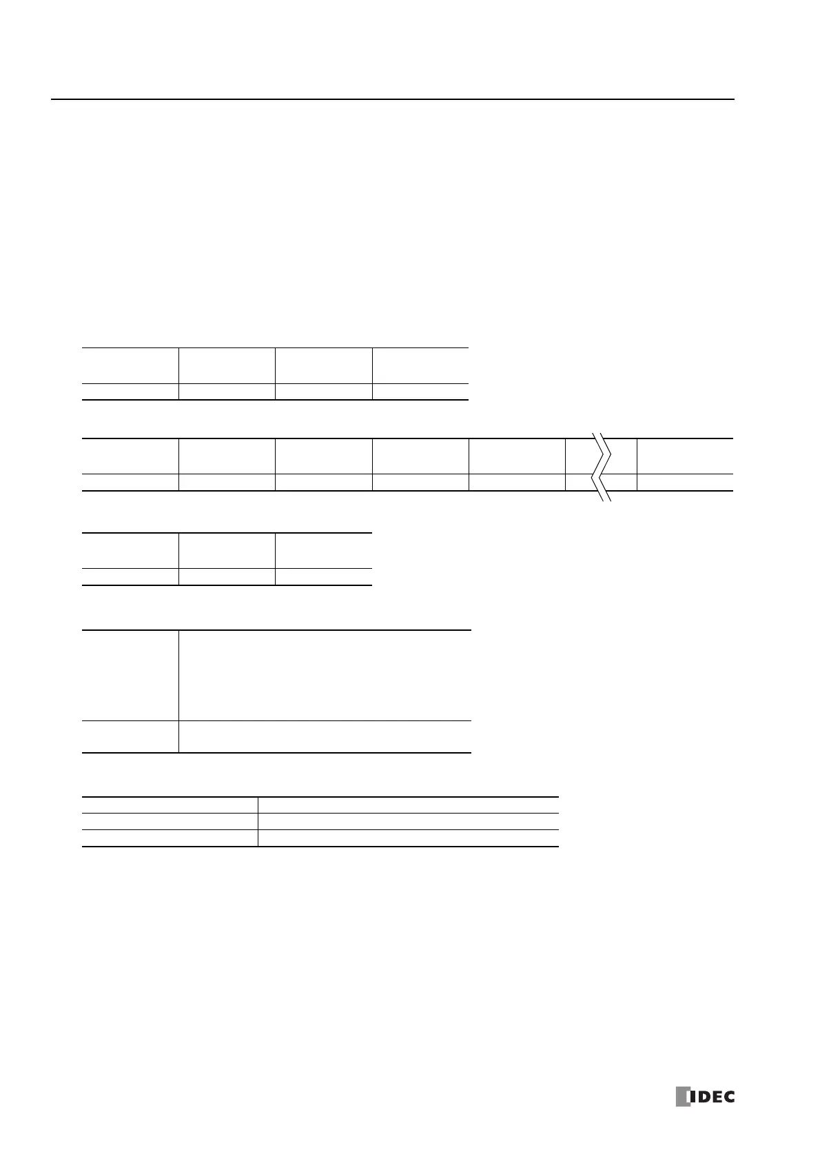
Request from Modbus Master 08 01 0008 0010 (CRC)
ACK Reply from Modbus Slave 08 01 02 34 12 (CRC)
NAK Reply from Modbus Slave 08 81 xx (CRC)
Slave No. Function Code Address No. of Bits
xxh 01h / 02h xxxxh xxxxh
Slave No. Function Code Quantity of Data First 8 Bits Second 8 Bits Last 8 Bits
xxh 01h / 02h xxh xxh xxh xxh
Slave No. Function Code Error Code
xxh 81h / 82h xxh

 Loading...

