CHAPTER 4:BATTERY CHARGING
•
Introduction
The pilot lamps should always be on during the
charging operation. If they are not, check to make
sure you have turned off both the transmitter and
receiver.
Do not use the charger for equipment other than JR.
The charging plug polarity may not be the same and
equipment damage may result.
Do not use other manufacturers’ after-market
accessories that plug into the transmitter’s charging
jack. If you do, any damage that results will not be
covered by warranty. If you are unsure of
compatibilities with your radio, seek expert advice
before doing anything to avoid possible damage.
During the charging operation, the charger’s
temperature is slightly elevated. This is normal.
CHARGER4.2
It is imperative that you fully charge both the
transmitter and the receiver battery packs prior to
each day of flying. For the initial charge, leave the
charger and batteries hooked up for 20-24 hours in
order to fully charge both battery packs to peak
capacity. For subsequent charges, leave the charger and
batteries hooked up overnight (approximately 16
hours).
The charger supplied with this system is designed to
recharge your transmitter battery at a rate of 50mA. The
receiver battery pack will charge at 50mA for the
600mAh airplane battery pack and at 150mA for the
1000mAh helicopter battery pack.
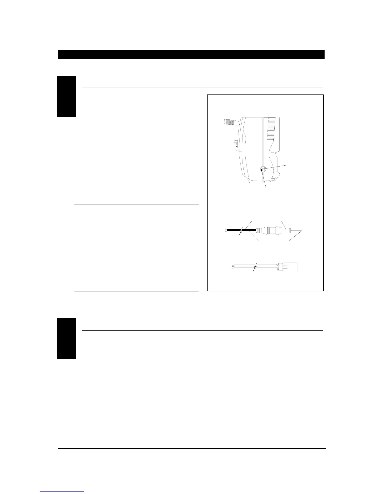
Transmitter Only
The center pin on all JR remote control systems is
negative. Therefore, the center pin on all JR
chargers is negative, not positive. This is different
from any other manufacturers’ chargers and radio
systems. Beware of improper connections based on
“color code” wire leads as they DO NOT APPLY in
this instance. You must make certain that the
center pin of your JR transmitter is always
connected to the negative voltage for correct
polarity hookup.

 Loading...