EasyManuals Logo
Home>JR>Remote Control>XP652

JR XP652 User Manual

JR XP652
96 pages
To Next Page IconTo Next Page
To Previous Page IconTo Previous Page
Page #57 background imageLoading...
Page #57 background image
57
SYSTEM MODE
CHAPTER 5:INPUT MODE AND FUNCTION
Helicopter
5.2
NORMAL DISPLAY5.1
XP652 MANUAL Helicopter
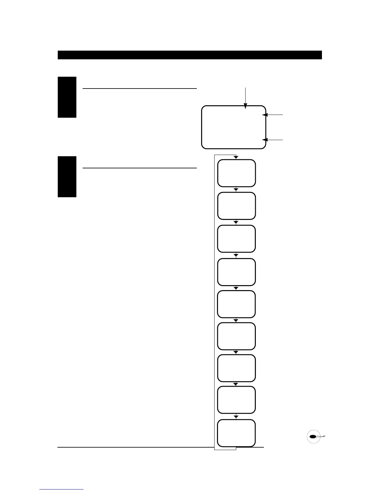
When the power switch is turned on the screen will
read as shown here in the diagram. This screen is
referred to as the normal display.
To enter the system mode press the MODE and
CHANNEL buttons simultaneously while you turn on
the transmitter. You can now select any of 8 system
mode functions shown here in the flow chart. To exit
the system mode, press the MODE and CHANNEL
buttons simultaneously or turn off the transmitter.
Press the MODE button to move through the system
mode functions. Information for each function is
located on the page number listed next to the
function name.
I0.4V
HE I
MODEL NUMBER
AC = FIXED WING AIRCRAFT
HE = HELICOPTER
BATTERY VOLTAGE
I
MDL
I
HEI
I
SPC
FST
HE
TYP
HE
RST
E.A
SW
D/R
F
GER
OF
FSI
MODEL TYPE SELECTION
Page 59
DATA RESET Page 60
DUAL RATE SWITCH
SELECTION
Page 61
GEAR/GYRO SWITCH
SELECTION
Page 62
MODEL SELECTION Page 63
MODEL NAME ENTRY
Page 64
MODULATION SELECT
Page 65
Page 66
*
(S-PCM)
*
(Z-PCM)
* Only visible when modulation type is selected for SPCM, or ZPCM modulation
FAIL-SAFE
FAIL-SAFE MEMORY
V
Page 68

Table of Contents

Questions and Answers:

Question and Answer IconNeed help?

Do you have a question about the JR XP652 and is the answer not in the manual?

JR XP652 Specifications

General IconGeneral
BrandJR
ModelXP652
CategoryRemote Control
LanguageEnglish

Related product manuals