button to adjust the pitch curve value.
screen. Press
throttle curve.
position.
and display are the same.
function is activated.
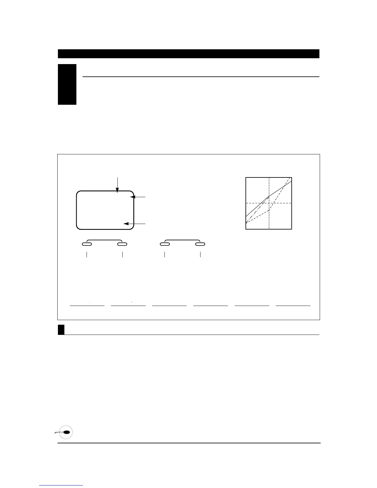
The XP652 offers 3 separate pitch curves with 3
adjustable reference points per curve. This function
allocates a separate pitch curve setting during
normal, stunt, and throttle hold modes to
maximize flight performance. Once the pitch curves are
established, each can be activated in flight using the
2-position flight mode switch and the throttle hold
switch.
Each of the 3 reference points of the pitch curve are
independently adjustable from 0–100%. These 3 points
correspond to the low, middle, and high positions of
the throttle stick (collective).
The graph below shows samples of pitch curves in the
normal (N), stunt (S) and throttle hold (H) conditions.
The factory preset values for all 3 pitch curves are:
Low 0%, Middle 50%, and High
100%.
1. Turn on the transmitter.
2. Press the MODE and CHANNEL buttons
simultaneously to enter the function mode.
3. Press the MODE button until PLN appears on the
screen. The letter to the far right indicates the
specific pitch curve section that you are in (N, S or
H). The letter in the center indicates the reference
point that you are in (L, 2 or H).
4. Press the CHANNEL button to select the reference
point of the pitch curve you want to change.
5. Press the INCREASE or DECREASE button to
change the value of the current reference point. The
range of each point is 0–100% in 1% intervals.
6. To set the pitch curve for the stunt (flight) mode,
press the MODE button once. Then, repeat Steps 5
and 6 to adjust.
7. To set the pitch curve for the throttle hold mode,
press the MODE button once. Then, repeat Steps 5
and 6 to adjust.
8. Press the mode button to access the throttle curve
function.
Note: If throttle hold is not activated, the throttle
curve function will be accessed.
9. To exit, press the MODE and CHANNEL buttons
simultaneously.
PITCH CURVE
•
Function Mode
7.7
N
N
N N

 Loading...