FX-1/FX-1R Maintenance Manual
DANGER
To prevent any trouble caused by accidental machine start, always
shut-down the power before starting the maintenance and
adjustment work.
[13] ELECTRICAL COMPONENTS
13-1. Layout of Electrical Components
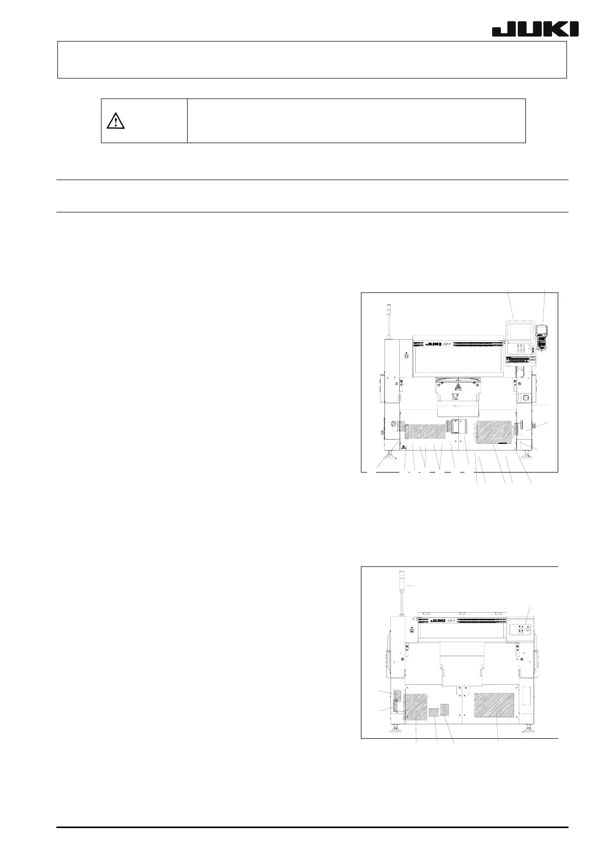
Figure 13-1-1 shows the front view and Figure 13-1-2 shows the rear view. (FX-1)
13-1-1. Part Names
1 3
14 17
16
15
13
18
5
6
19
12
11 10 9 8
7
1. Operation unit
LCD monitor, Operation switch board (For front)
EMERGENCY STOP switch, Keyboard, Trackball
2. Operation panel
[Front: LCD monitor, operation board]
[Rear: Operation switch board]
3. HOD 4. Signal tower
5. Power switch 6. CD-ROM
7. FDD 8. HDD
9. Control unit
[CPU board, Position board, Bus bridge board,
MCM (4-axis), SAFETY board, BaseFeeder board,
I/O control board, LIGHT CTRL board, IP-X3
board, C-PCI Board, VME Back Board
Figure 13-1-1 Front View
10. Scale I/F board
11. Position relay board
12. Magnescale detector (FX-1)
Scale PCB (FX-1R)
13. Scale I/F unit (YBL, YBR, XL, XR) (FX-1)
Scale I/F unit (YA, YBL, YBR, XL, XR) (FX-1R)
25
24
23
22
4
2
20
21
14. X-axis AC servo driver (XL, XR)
15. YB-axis AC servo driver (YBL, YBR)
16. YA-axis AC servo driver
17. AC stepper driver (STBL)
18. DC stepper driver (CENT, AWCC, AWCS)
19. Console splitter (Optional)
20. Circuit breaker
21. Noise filter
22. Transformer
23. Safety unit (EN specification only)
24. UPS (Uninterruptible power supply)
Figure 13-1-2 Rear view
25. Power supply unit
13-1
Rev. 2.00
 Loading...


