FX-1/FX-1R Maintenance Manual
2-3. Replacing the Z-Sensor
After the Z-sensor has been replaced, it is absolutely necessary to re-input MS parameters related
to the height of the Z-axis. (For details about input items, see section 2-9.)
2-3-1. MNLA Head
(1) Remove the peripheral components
following the steps (1) to (5) in the
section 2-1-1.
(2) Remove the Z-sensor base mounting
screws (2 pcs.) and detach the
Z-sensor base downward.
(3) Cut the tie-up band to replace the
Z-sensor.
Reassemble the
components in the
reverse order of disassembly.
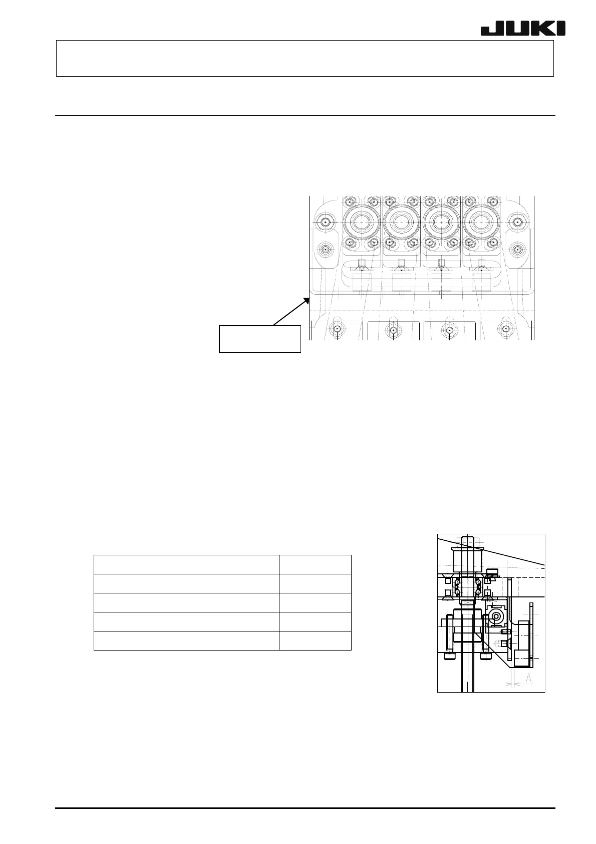
Z-sensor base
Figure 2-3-1
(4) Check following the procedure below
and make adjustments if necessary.
<Procedure>
c Loosen the Z-sensor base mounting screws and adjust the Z-sensor position so that the
clearance between the Z-sensor and Z-sensor dog (dimension A in the figure below) is 1.4 ±
0.1mm.
Move the Z-sensor dog up and down to check that the values measured at the upper and
lower positions are within 1.4 ± 0.1 mm.
Table 2-3-1
Part name Part No.
Z1-DECELERATION SENSOR CABLE ASM L817E9210A0
Z2-DECELERATION SENSOR CABLE ASM L818E2210A0
Z3-DECELERATION SENSOR CABLE ASM L818E6210A0
Z4-DECELERATION SENSOR CABLE ASM L818E9210A0
Figure 2-3-2
2-7
Rev. 2.00
 Loading...


