FX-1/FX-1R Maintenance Manual
14-2. Assembling to the Machine Main Unit
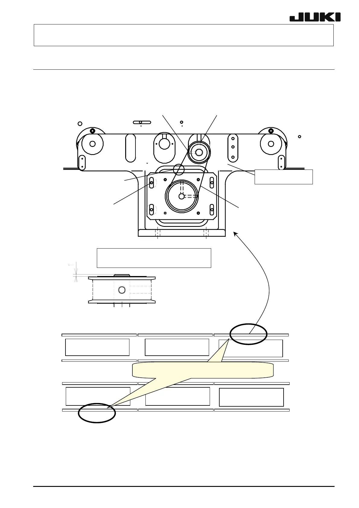
14-2-1. Mounting the AWC Bracket Assembly
E4561729000
WC SHAFT PULLEY
L173E721000
AWC MOTOR BELT
SL6051492TN
BRKT FIX BOLT ×4
Belt tension measuring point
RAIL STAND RR
SM8040402TP
SET SCREW×2
Figure 14-2-1-1
14-2
Shaft of the IN/OUT ball screw is
projected 1.0 mm from the pulley.
Driven rail
IN/OUT BUFFER IN/OUT BUFFER CENTER BUFFER
IN/OUT BUFFER IN/OUT BUFFER CENTER BUFFER
Front reference
Rear reference
WC motor and sensor mountin
ositions
Reference rail
Reference rail
Driven rail
Figure 14-2-1-2
Assemble the components so that the end face of the IN/OUT ball screw is projected 1.0 mm from
the AWC shaft pulley.
The same assembly method applies regardless of the transport reference and flow direction.
Rev. 2.00
 Loading...


