FX-1/FX-1R Maintenance Manual
13-9-3. Mounting the Switches on the OPERATION SW PCB ASM
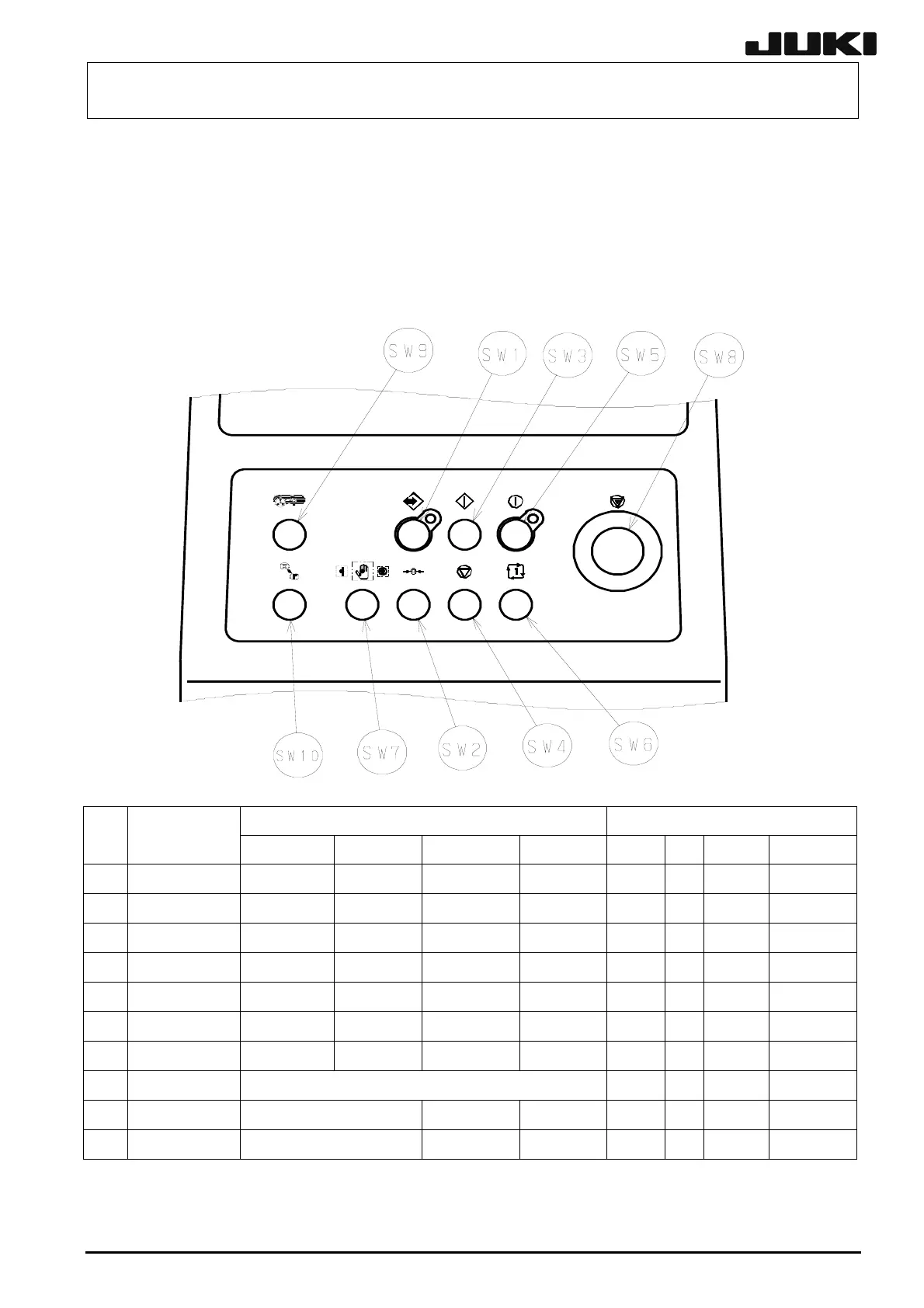
According to the specification, mount the pushbutton switches SW1 to SW7 on the sockets on the
OPERATION SW PCB ASM as shown in the figure below.
13-9-3-1. Structure
(1) Front
Switch components Specification
No Switch name
Actuator LED Lense/Front Bezel Standard EN Rear OP
NON-STOP OP
SW1 ONLINE
HA005340020 HA00534006A HA00552001B HA00534004A
{ { { {
SW2 ORIGIN
HA005340020 HA005340060 HA00552001A HA005520030
{
{ { {
SW3 START
HA005340020 - HA00552001B HA005520030
{
{ { {
SW4 STOP
HA005340020 - HA005520010 HA005520030
{
{ { {
SW5 SERVO FREE
HA005340020 HA005340060 HA00552001A HA00534004A
{
{ { {
SW6 CYCLE
HA005340020 HA00534006A HA00552001B HA005520030
{
{ { {
SW7 SET UP
HA005350020 - HA00535003A HA005520020 -
{
{ {
SW8 EMERGENCY
L833E7210A0
{
{ { {
SW9 BANK ENABLE
40002252 HA005530020 HA005530010 - - -
{
SW10 F/R SELECT
40002251 HA00553002A HA005530010 - -
{
-
13-36
Rev. 2.00
 Loading...


