FX-1/FX-1R Maintenance Manual
13-4-5. MCM (Multi Nozzle Control Module) Board (E9609729000)
[Functions]
This board controls the part centering sensors (MNLA).
Two 4-axis MCM boards for the MNLA (E9609729000) are used (for left and right heads).
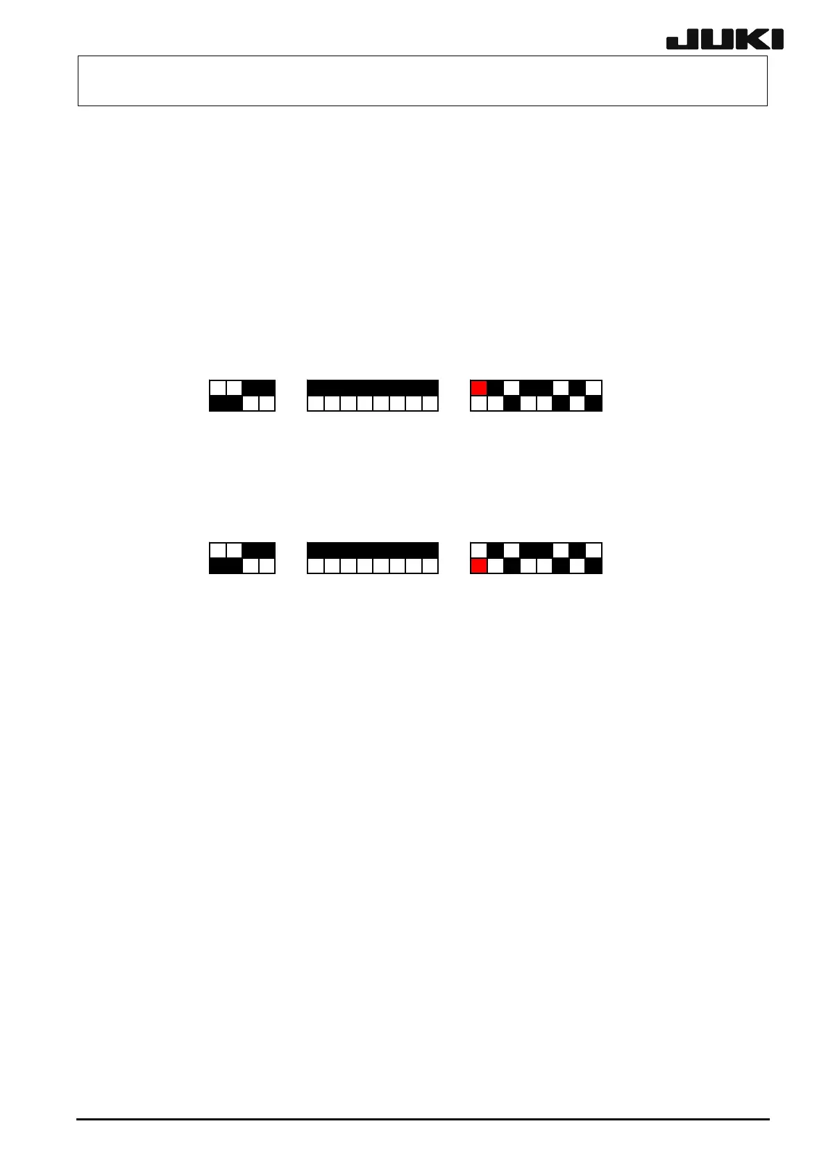
[Switch settings]
MCMR(左)
S3 S2 S1
1234 12345678 12345678
ON
MCMR(右)
S3 S2 S1
1234 12345678 12345678
ON
MCMR (for Right)
MCMR (for Left)
[LEDs on front panel]
All LEDs are lit at start-up. After that, the “SEN PWR”, “AB0”. “AB1”, “AB2”, and “AB3” LEDs will
go off in that order. In the normal status, only the “+24” LED is lit.
[Adjustment items after replacement]
Follow the steps below to update the FLASH memory.
c Select [Options] and [Change User Group], and then select [Serviceman].
d Select [Maintenance] and [MS Parameter Setup].
e Select [Others], [Version-up], and [MCM/MCMR].
13-11
Rev. 2.00
 Loading...


