FX-1/FX-1R Maintenance Manual
e Set the adjustment screw to the center between positions A and B.
c Position A d Position B e Set position
MAX
MIN MAX MINMAX
MIN
Figure 5-9-2
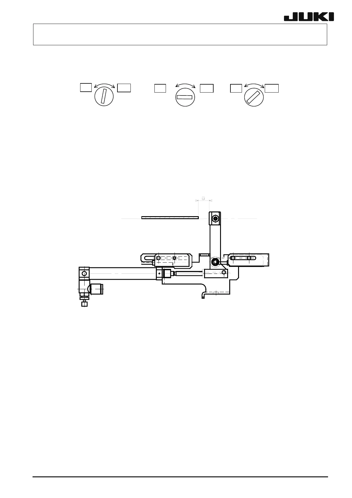
(5) Perform the fine adjustment of the sensor position.
c Select [Manual Control] and [Individual Transfer Control] in that order to turn ON the
stopper and raise the stopper.
d
With manual operation, gradually load a PWB. Move the sensor position so that the
distance from the sensor ON position to the stopper tip becomes dimension “a”
(25±1mm).
Figure 5-9-3
5-13
Rev. 2.00
 Loading...


