KE-2050/KE-2060, KE-2050R/2055R/KE-2060R Maintenance Manual
14-33
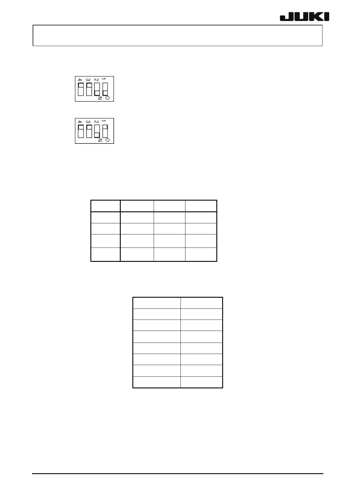
For JHRMB, set the DIP switches (SW1) according to the board type.
DIP switch settings on the ZT driver board (Zθ 1 to 4: For MNLA axis)
DIP switch settings on the ICZT driver (IC Zθ: For FMLA axis)
14-6-2. LED Indications
Four LEDs are provided at the upper portion of the front panel of the Z/θ driver board. These LEDs
show the operating status of each axis as shown below. The correspondence among the axes and
LEDs are as follows.
Z1 Z2 Z3
1 Z1 Z3 Z5
2 θ1 θ3 θ5
3 Z2 Z4
−
θ2 θ4
−
• Green: Servo lock
• Orange: Servo lock OFF
• Red: Alarm
If an alarm has occurred, the LED corresponding to the alarm axis indicates the type of the alarm
by the blinking count as shown below.
Blinking count
Overcurrent 1
Overload 2
Overvoltage 3
Driving power off 4
Overheat 5
Encoder error 6
Commutation error
7
Rev. 2.00

 Loading...


