KE-2050/KE-2060, KE-2050R/2055R/KE-2060R Maintenance Manual
1-28
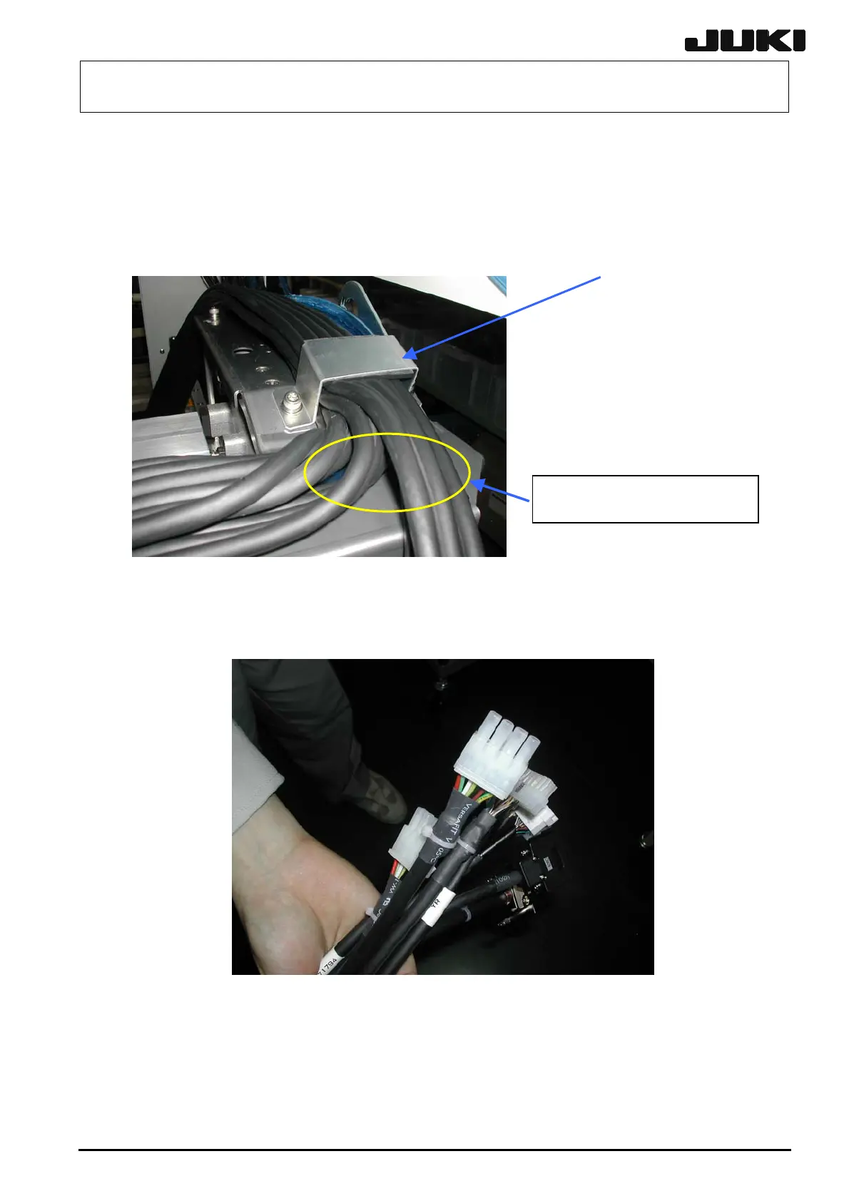
1-8-7. Assembling the Y Cable Bearer
(1) Place the 40002232 cables on the cables routed from the X-axis so that its CN166 side is
located inside (Figure 18-8-1). Equate the lengths of the swing part relay connectors for
40002234 and 40002232 (Figure 18-8-2). Then fix them with the cable clamp YB.
Fix with the cable clamp YB so
that the cables do not stand out.
Cable clamp YB
Figure 1-8-7-1
(2) Pull out the cables to the front side and align the connectors for 40002234 with the connector
bracket relay connectors (CN161/CN151/CN127/CN165 sides) for 40002232.
Figure 1-8-7-2
Rev. 2.00

 Loading...


