KE-2050/KE-2060, KE-2050R/2055R/KE-2060R Maintenance Manual
14-30
14-5-2. LED Indication
Two LEDs are equipped in the front panel upper
part of the XY driver board.
Table 14-5-2-1
Alarm description Blinking count
Overcurrent 1
Overload 2
Overvoltage 3
Driver power OFF 4
Overheat 5
Fault in encoder 6
Encoder improperly connected 7
One XY driver board has a driving function which
can drive two axes, the X-axis and the Y-axis,
independently. The LED 1 is for the X-axis; the
LED 2 is for the Y-axis.
The alarm description is indicated by how many
times the LED blinks in red. (See Table 14-5-2-1.)
For example, if the LED is blinking in such an order
as "green, red, red, red, green, red, red, red,
green...", the number of times LED blinks in red is
"3". This means an "overvoltage" error.
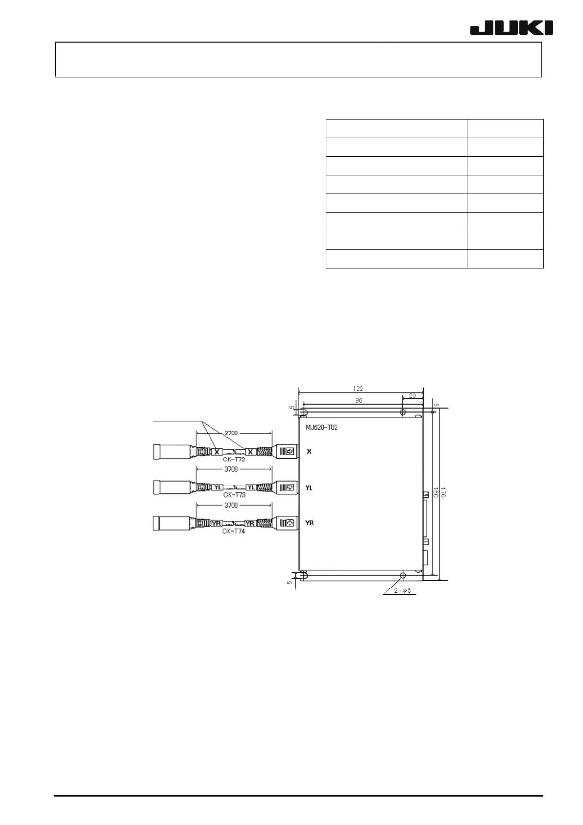
14-5-3. DIP Switch Settings on the Magnescale
Figure 14-5-3-1 shows the layout of the magnescale interpolator. If an error occurs, the LEDs
(D102, D202, D302, and D402) are lit in red. To replace the magnescale detector, remove the
screws at four corners.
Marker tube
Figure 14-5-3-1 Magnescale
(with the detector viewed from the left of the machine)
Rev. 2.00

 Loading...


