KE-2050/KE-2060, KE-2050R/2055R/KE-2060R Maintenance Manual
1-33
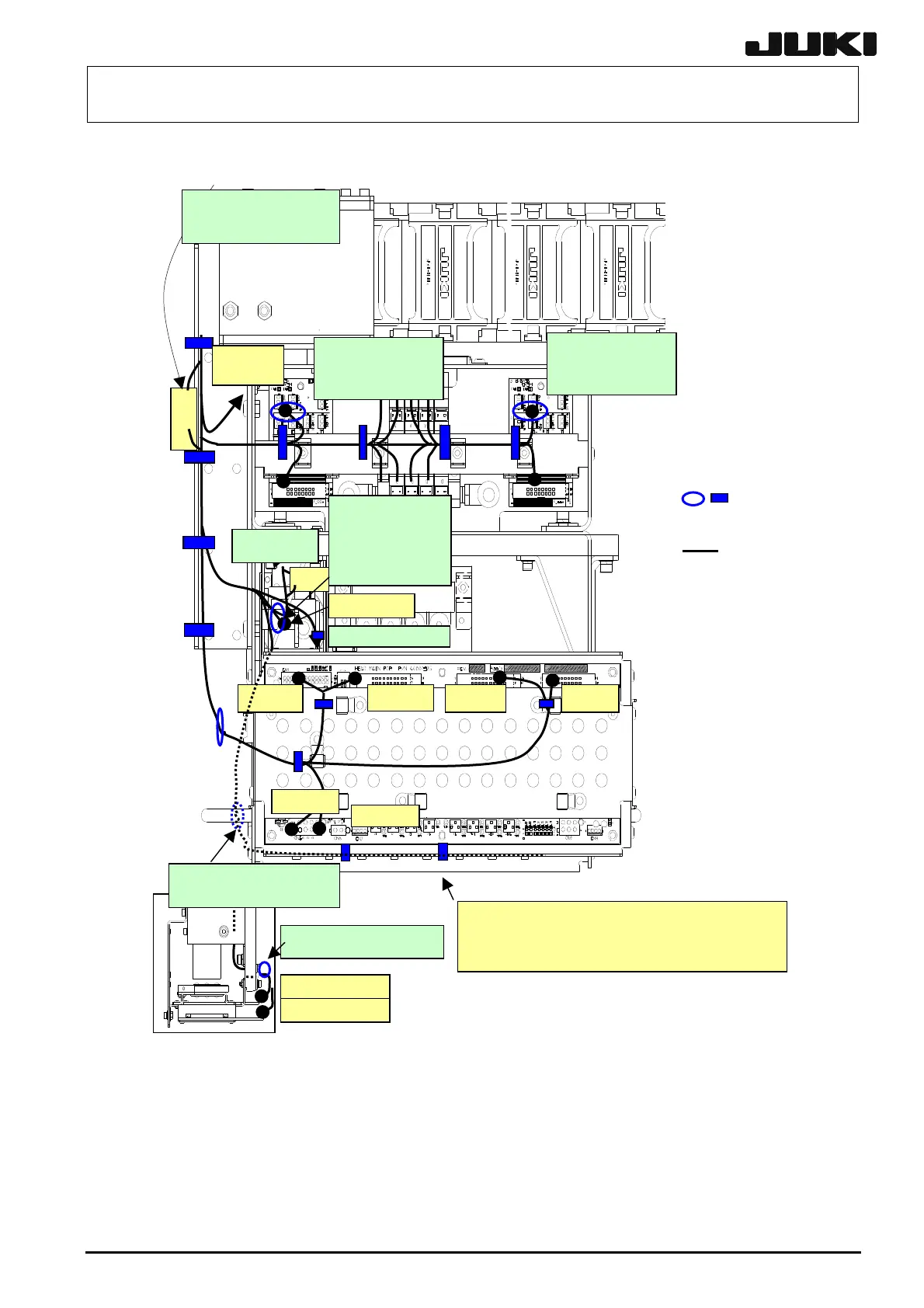
1-8-8. Wiring around the Head
CN803 CN804
CN806
CN805
CN802CN801
CN849
X
OCCA (L)
OCCV (L)
lso clamp the magnescale
and MNLA cables together.
To MNLA Z sensor
Clamp the cables on
the board in a bundle
within 50mm of the
connector.
See the figure
below.
Cables to be
clamped to the
camera bracket U:
• Magnescale
• OCC light, camera
• MNLA
Clamp to the screw-fastened
fixture base tightened togethe
with the head handle.
Plug the Z and θ connectors of the motor starting
from the left in the order of CN209, CN210, ...,
CN216. (Plug into the connector bracket 50 from
bottom to top.)
Clamp the cables on
the board in a bundle
within 50mm of the
connector.
Cable
Tie-up band
To the OCC
relay board.
OCC (L)
The CN849 connector
shall not protrude in the
left of the FC guide.
Figure 1-8-8-1 KE-2050/2050R/2055R
(1) Clamp the cables following the figure above. Use the large tie-up band for the FC guide, and
the small tie-up band for other parts. When clamping, take care not to apply undue bending nor
load to the cables. If some part is covered with a cable protective sheet, tie up the cables within
the width of the sheet.
Rev. 2.00

 Loading...


