KE-2050/KE-2060, KE-2050R/2055R/KE-2060R Maintenance Manual
2-23
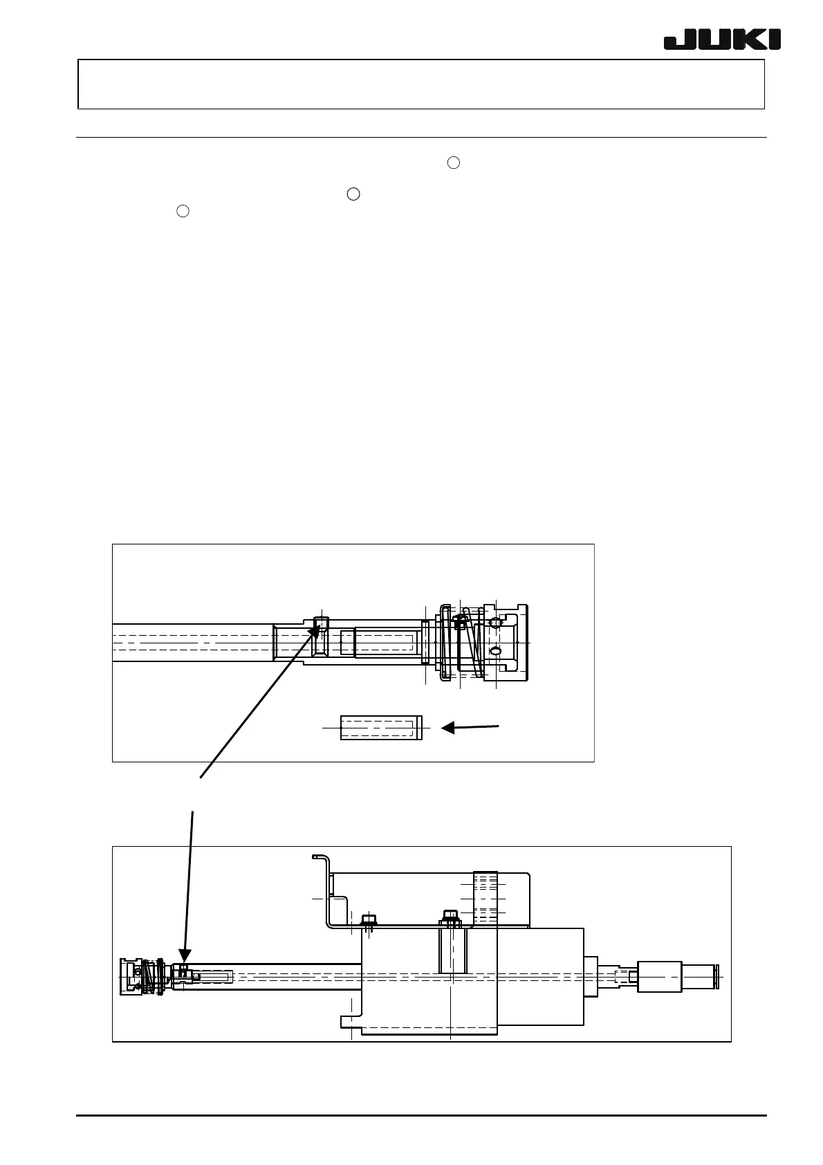
2-8. Replacing the Nozzle Outer Shaft Assembly
(1) Loosen the nozzle outer shaft mounting screw
17
to detach the nozzle outer shaft.
(2) When attaching, insert the filter
18
into the shaft as far as it will go and fix it with the mounting
screw
17
.
(3) If you attach a new nozzle outer shaft, follow the procedure below.
(4) After the replacement work has been completed, follow the steps stated in section 2-9 to obtain
the MS parameters again.
<Procedure>
c Attach the jig nozzle to the head.
d Place a dial gauge over the jig nozzle and check that the run-out of the nozzle outer shaft is
within 0.02 mm.
If the run-out is 0.02 mm or more, move the screw position and scribing line of the spline shaft
to find a position where the run-out becomes 0.02 mm or less. With a combination having a
run-out of 0.02 mm, write a new scribing line on the shaft side.
Conduct work holding the black part of the spline shaft. If it is necessary to touch the
silver part of the spline shaft, do not touch with bare hands but use gloves or the like.
Tighten the nozzle outer shaft mounting screw with a tightening torque of 0.5 Nm.
Figure 2-8-1 MNLA Head
⑱
⑰
Figure 2-8-2 FMLA Head
Rev. 2.00

 Loading...


