KE-2050/KE-2060, KE-2050R/2055R/KE-2060R Maintenance Manual
2-13
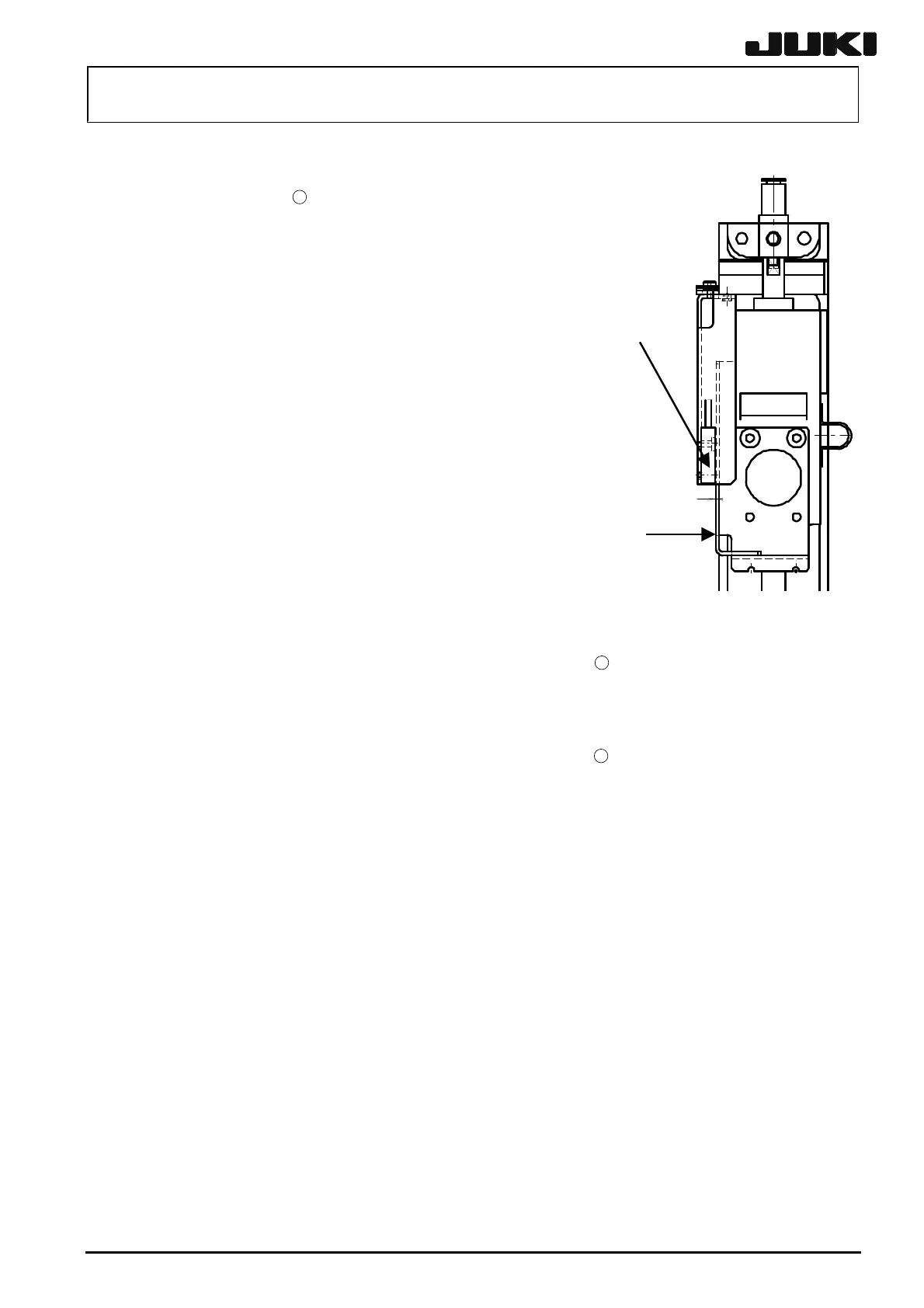
<Procedure>
c Measure the clearance between the Z-sensor and
Z-sensor dog IC
16
. Move the Z-sensor dog up and
down to check that the values measured at the upper
and lower positions are within 0.9 ± 0.2 mm.
(Dimension A)
Z-sensor dog
A
d If the values are out of the specification range,
loosen the Z-sensor base mounting screws and
adjust the Z-sensor position. If the clearance value
changes as the IC θ-motor is moved vertically,
loosen the mounting screws and adjust the
orientation of the Z-sensor dog.
Z-sensor
e With the ICZ-motor and head-up SPIC not mounted,
check using a spring scale that the Z-sensor dog
slides at 0.75kg.
Apply Loctite 242 to the IC θ-motor mounting screws
After tighten the half union manually, turn it with a wrench one-sixth turn.
15
(4 pcs.) and tighten them with
a tightening torque of 1.3 Nm. At this time, exercise care to avoid any clearance from
being formed between the reference surface of the motor and that of the linear guide.
The cable of the motor should be located on the left side when viewed from the front.
Apply Loctite 242 to the ball screw mounting screws
14
(4 pcs.) and tighten them with
a tightening torque of 3.7 Nm.
Attach the head following the section 2-1-2.
After that, adjust the distance between the head centers.
Rev. 2.00

 Loading...


