CHAPTER 12
Installing Modules
•
CTP2000 Modules Installation Overview on page 87
•
Protecting CTP2000 Modules and Slots on page 87
•
Required Tools and Safety Items for Installing CTP Modules on page 88
•
Installing a CTP Interface Module, Processor Module, or Clock Module on page 89
•
Removing a CTP Interface Module, Processor Module, or Clock Module on page 89
•
Installing or Removing a CTP2000 Series CompactFlash Card on page 90
•
Installing a PMC on CTP2000 Platforms on page 92
CTP2000 Modules Installation Overview
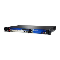
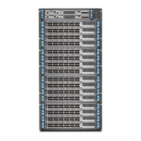
In CTP2000 platforms, you can install interface modules in the front and rear of the
device.
Related
Documentation
Protecting CTP2000 Modules and Slots on page 87•
• Required Tools and Safety Items for Installing CTP Modules on page 88
• Safety Guidelines and Warnings for Installing CTP Modules on page 69
• Installing a CTP Interface Module, Processor Module, or Clock Module on page 89
• Installing or Removing a CTP2000 Series CompactFlash Card on page 90
• Installing a PMC on CTP2000 Platforms on page 92
• Installing SFPs in a CTP2000 Module on page 95
Protecting CTP2000 Modules and Slots
To prevent damage from electrostatic discharge, wear an antistatic wrist strap, and
connect it to one of the jacks when handling components. The CTP2056 has an ESD
(electrostatic discharge) grounding jack located in the rear lower-left corner of the chassis
near the power switch. There are no ESD jacks on the other CTP2000 platforms, so you
must use another grounding device.
To protect the modules, components, and slots when installing components, observe
the following guidelines:
87Copyright © 2017, Juniper Networks, Inc.

 Loading...


