Home
Juniper
Network Hardware
CTP2000 Series
Juniper CTP2000 Series Hardware Documentation
4
of 1
of 1 rating
150 pages
Give review
Manual
Specs
To Next Page
To Next Page
To Previous Page
To Previous Page
Loading...
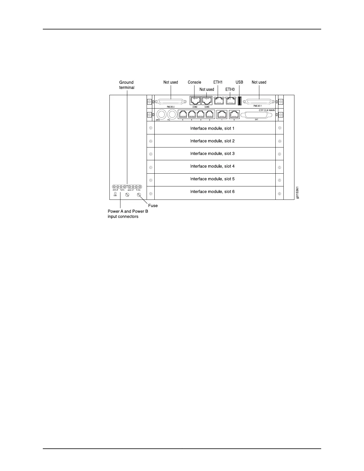
Figure
10:
CTP2056
Pla
tf
orm
Containing
the
PP332
Proc
essor
(DC
V
ersion,
R
ear
V
iew)
R
elat
ed
Documenta
tion
•
CTP2008
Pla
tf
orm
on
page
4
•
CTP2024
Pla
tf
orm
on
pag
e
5
Cop
yright
©
2017
,
Juniper
Netw
orks,
Inc.
10
CTP2000
Hardware
Documentation
25
27
Table of Contents
Default Chapter
3
Table of Contents
3
About the Documentation
11
Documentation and Release Notes
11
Documentation Conventions
11
Table 1: Notice Icons
12
Table 2: Text and Syntax Conventions
12
Documentation Feedback
13
About the Documentation
13
Requesting Technical Support
14
Self-Help Online Tools and Resources
14
Opening a Case with JTAC
14
CTP2000 Series Interface Modules
17
CTP2000 Series Platform Overview
17
Overview
17
Chapter 1 CTP2000 Series Platform Overview
19
Introducing CTP Platforms
19
CTP2000 Series Processor
19
CTP2008 Platform
20
Figure 1: PP833 Processor (AC and DC Version, Front View)
20
Figure 2: CTP2008 Chassis Containing the PP332 Processor (AC and DC Version, Front View)
20
Interface
20
CTP2024 Platform
21
Figure 3: CTP2008 Platform Containing the PP332 Processor
21
Figure 4: CTP2008 Platform Containing the PP332 Processor
21
Figure 5: CTP2024 Chassis Containing the PP332 Processor
22
CTP2056 Platform
23
Figure 6: CTP2024 Platform Containing the PP332 Processor
23
Figure 7: CTP2024 Platform Containing the PP332 Processor
23
Interface
23
Figure 8: CTP2056 Chassis Containing the PP332 Processor (AC and DC Version, Front View)
24
Interface
24
Figure 9: CTP2056 Platform Containing the PP332 Processor
25
Figure 10: CTP2056 Platform Containing the PP332 Processor (DC Version, Rear View)
26
Chapter 2 CTP2000 Series Interface Modules
27
CTP2000 Serial Interface Modules
27
Figure 11: Sample Serial Interface Module
27
CTP2000 T1/E1 Interface Module
28
CTP2000 Compression Interface Module
28
Figure 12: CTP2000 IM-8P-T1/E1 Interface Module
28
Figure 13: Compression Interface Module
28
CTP2000 Compression 2 High Density Interface Module
29
CTP2000 4WE&M Interface Module
30
Figure 14: CTP2000 4WE&M Module
30
Figure 15: 4WE&M RTM
30
Figure 16: Jumper Locations on the RTM
31
Figure 17: Jumper Positions for Signaling Types
31
Table 3: Jumper Positions for Configuring Port Signaling Type
31
Supervisory Signaling
33
Table 4: Signal Definitions
33
Figure 18: Analog 4WE&M Signaling Types
34
CTP2000 2W-FXS and 2W-FXO Interface Modules
35
Table 5: Supported Signaling Types for the CTP2000 4WE&M Module
35
Analog FXS/FXO Loop-Start Signaling
36
Figure 19: Front Panel of CTP2000 2W-FXS Interface Module
36
Figure 20: Rear Panel of CTP2000 2W-FXS RTM
36
Figure 21: Front Panel of CTP2000 2W-FXO Interface Module
36
Figure 22: Rear Panel of CTP2000 2W-FXO RTM
36
Answer Supervision
37
Disconnect Supervision
37
Required Cables and Pinouts
36
Analog FXS/FXO Ground-Start Signaling
37
Digital Signaling
38
Digital FXS/FXO Loop-Start Signaling
38
Digital FXS/FXO Ground-Start Signaling
39
Table 6: Ground-Start Signaling at FXO Interface for Call Initiated by the FXO
39
Table 7: Ground-Start Signaling at FXO Interface for Call Initiated by the FXS
39
Table 8: Ground-Start Signaling at FXS Interface for Call Initiated by the FXS
40
Table 9: Ground-Start Signaling at FXS Interface for Call Initiated by the FXO
40
CTP2000 8P-IRIG Interface Module
41
CTP2000 Clock Interface Modules
41
Figure 23: CTP2000 8P-IRIG Interface Module
41
Interface
41
Figure 24: Clock Main Module
42
Figure 25: Clock Spoke Module
42
Figure 26: Hub-And-Spoke Setup
42
External Reference Clock
43
Installation Notes for Clock Interface Modules
43
Planning
45
System Specifications
45
Cable and Pinout Specifications
45
Chapter 3 System Specifications
47
CTP2008 Platform Specifications and Certification
47
Table 10: CTP2008 Platform Specifications
47
CTP2024 Platform Specifications and Certification
49
Table 11: CTP2024 Platform Specifications
49
CTP2056 Platform Specifications and Certification
50
Table 12: CTP2056 Platform Specifications
50
Chapter 4 Planning and Preparing the Site
53
Before You Install a CTP Platform
53
CTP2000 Environmental Requirements
53
Chapter 5 Equipment Rack Requirements
55
CTP2000 Rack Requirements
55
CTP2000 Mechanical Requirements
55
CTP2000 Space Requirements
56
CTP2000 Rack Installation
56
CTP Cabling Recommendations
56
Chapter 6 Cable and Pinout Specifications
59
CTP2000 4WE&M Interface Connector Pinouts
59
CTP2000 4WE&M RTM Connector a Pinouts
59
Table 13: CTP2000 4WE&M RTM Pinouts-Connector a
59
CTP2000 4WE&M Connector B Pinouts
60
Table 14: CTP2000 4WE&M RTM Pinouts-Connector B
60
CTP2000 FXS and FXO Interface Module Cables and Pinouts
61
Required Cables
61
RTM Pinout Locations
61
FXS Connector Pinouts
62
Figure 27: RTM Pinouts for CTP2000 2W-FXS and 2W-FXO Interface
62
Table 15: CTP2000 FXS Connector Pinouts on the RTM
62
FXO Connector Pinouts
63
Table 16: CTP2000 FXO Connector Pinouts on the RTM
63
T1/E1 Interface Module Pinouts
64
Table 17: T1/E1 Interface Module-RJ-45 Connector Pinout
64
CTP2000 Serial Interface Module Pinouts
65
Figure 28: CTP2000 Serial DCE/DTE Cable Pin Configurations
65
Table 18: CTP2000 Serial DCE Cable Pinouts
66
Table 19: CTP2000 Serial DTE Cable Pinouts
70
CTP2000 Series Console Cable Pinouts
74
Table 20: CTP2000 Series Console Cable Pinouts for PP310 and PP332
75
Table 21: CTP2000 Series Console Cable (P/N 720-071594) Pinouts for the
75
Figure 30: Upgrading from PP310/PP332 Processor to PP833 Processor
77
Figure 31: Connecting the PP833 Processor with the RJ-45 Serial Console
78
Figure 32: Connecting the PP833 Processor with the PC DB-9M Serial
78
CTP Fast Ethernet and Power Cables
79
Fast Ethernet Cables
79
DC Power Cables
79
Safety
81
Chapter 7 General Safety Guidelines and Warnings
83
CTP Safety Guidelines and Warnings
83
Chapter 8 Module Installation Safety Guidelines and Warnings
85
Safety Guidelines and Warnings for Installing CTP Modules
85
Chapter 9 Hardware Compliance
87
Declaration of Conformity for CTP2000 Platforms
87
Figure 33: CTP2000 Declaration of Conformity
88
Federal Communications Commission (FCC) Statement
89
FCC Requirements for Consumer Products
89
Food and Drug Administration, Center for Devices and Radiological Health
90
Compliance with Canadian Regulations
90
Industry Canada Notice
90
Industry Canada Notice CS-03
90
Avis CS-03 D'industrie Canada
91
Canadian Department of Communications Explanatory Notes
91
DOC Explanatory Notes: Equipment Attachment Limitations
91
Notes Explicatives du Ministère des Communications: Limites Visant les
91
Accessoires
91
Chapter 10 Unpacking and Inspecting the CTP Platform
95
Before You Unpack the CTP Platform
95
Unpacking the CTP Device
95
Inspecting Platform Components and Accessories
96
If You Detect or Suspect Damage
96
Contacting Juniper Networks
97
Chapter 11 Installing the Chassis
99
Before You Install the CTP2000 Platform
99
Installing the CTP2000 Platform in Freestanding Mode
99
Special Guidelines for Installing CTP2056 Chassis in a Rack
100
Installing the CTP2000 Platform in a Rack
100
Chapter 12 Installing Modules
103
CTP2000 Modules Installation Overview
103
Protecting CTP2000 Modules and Slots
103
Required Tools and Safety Items for Installing CTP Modules
104
Installing a CTP Interface Module, Processor Module, or Clock Module
105
Removing a CTP Interface Module, Processor Module, or Clock Module
105
Installing or Removing a CTP2000 Series Compactflash Card
106
Figure 34: Installing Compactflash on the PP833 Processor
107
Figure 35: Compactflash on the RTM
107
Installing a PMC on CTP2000 Platforms
108
Figure 36: CTP2000 Platforms PMC Location
108
Installing a CTP Interface Module, Processor Module, or Clock Module
108
Chapter 13 Installing and Removing Sfps in a CTP Module
111
Installing Sfps in a CTP2000 Module
111
Removing Sfps in a CTP2000 Module
112
Figure 37: Representative SFP
112
Figure 38: Possible Release Mechanisms on the SFP
113
Chapter 14 Upgrading Components for Memory Upgrades
115
Upgrading CTP2000 Series Components for Memory Upgrades
115
Chapter 15 Cabling
117
Cabling the CTP2000 Platform Overview
117
Required Tools, Wires, and Cables for the CTP2000 Platform
118
CTP2000 Management Ports
118
Cabling a CTP2000 Interface Module
119
Cabling the CTP Platform for DC Power
119
And Pinout Specifications
119
Connect Grounding Wires to the Chassis
119
CTP2000 Management Ports
119
Task 1: Turning off All CTP Platform Power
120
Task 2: Connecting the Grounding Cable to the CTP Platform (CTP2056 Platform Only)
120
Cabling a CTP2000 Interface Module
121
Task 3: Connecting the Power Cables to the CTP2000 Platform
121
Chapter 16 Powering on
123
Before You Power on the CTP2000 Platform
123
Powering on the CTP2000 Platform
123
Powering off the CTP Platform
126
Chapter 17 Accessing the CTP2000 Platform
127
Setting up Management Access on the CTP2000 Platform
127
CTP2000 Console Port Setup
128
Using Hyperterminal with the CTP2000 Platform
129
Connecting Directly to the CTP2000 Platform
129
CTP2000 Platform SSH Setup
130
Chapter 18 Maintaining Components
133
Required Tools for Maintaining the CTP Platform
133
Storing CTP Modules and Other Components
133
Cleaning the CTP Platform
134
Replacing an AC Power Supply
134
Figure 39: Replacing an AC Power Supply
135
Chapter 19 Replacing Interface Modules Using Hot-Swap
137
CTP2000 Hot-Swap Interface Module Replacement
137
Chapter 20 Product Reclamation and Recycling
139
Product Reclamation and Recycling Program
139
Chapter 21 Replacing Fan Trays
141
Removing a CTP2000 Fan Tray
141
Installing a CTP2000 Fan Tray
141
Chapter 22 Packing and Returning Hardware
143
Return Procedure
143
Returning CTP Products for Repair or Replacement
143
Troubleshooting
145
Chapter 23 Troubleshooting Power Failures
147
CTP Platform Does Not Power on
147
CTP Platform Shuts down
147
Chapter 24 Contacting Customer Support
149
Locating CTP Component Serial Numbers
149
Information You Might Need to Supply to JTAC
150
Other manuals for Juniper CTP2000 Series
Quick Start Guide
27 pages
Hardware Guide
149 pages
Upgrade
26 pages
4
Based on 1 rating
Ask a question
Give review
Questions and Answers:
Need help?
Do you have a question about the Juniper CTP2000 Series and is the answer not in the manual?
Ask a question
Juniper CTP2000 Series Specifications
General
Brand
Juniper
Model
CTP2000 Series
Category
Network Hardware
Language
English
Related product manuals
Juniper CTP2024
150 pages
Juniper CTP1000 Series
150 pages
Juniper SSR130
18 pages
Juniper NFX250
230 pages
Juniper SSR120
87 pages
Juniper MX10016
32 pages
Juniper ACX7100
12 pages
Juniper MX10004
14 pages
Juniper EX4100-F- 24P/T
9 pages
Juniper Day One+ QFX5120
12 pages
Juniper MX240 - UPGRADING
35 pages
Juniper Day One Plus SRX380
9 pages