To remove an AC power supply (see Figure 39 on page 119 for a representative AC power
supply at the rear of the chassis):
1. Switch off the dedicated customer site circuit breaker for the power supply, and
remove the power cord from the AC power source. Follow the instructions for your
site.
2. Attach an electrostatic discharge (ESD) grounding strap to your bare wrist, and connect
the strap to one of the ESD points on the chassis.
3. If the chassis has a power switch, move it to the off (O) position.
4. Unplug the power cord from the power source receptacle.
5. Unplug the power cord from the appliance inlet in the chassis above the power supply.
6. The AC power supply has a pull handle and a locking tab. Press the locking tab to the
right while you pull the unit out using the handle.
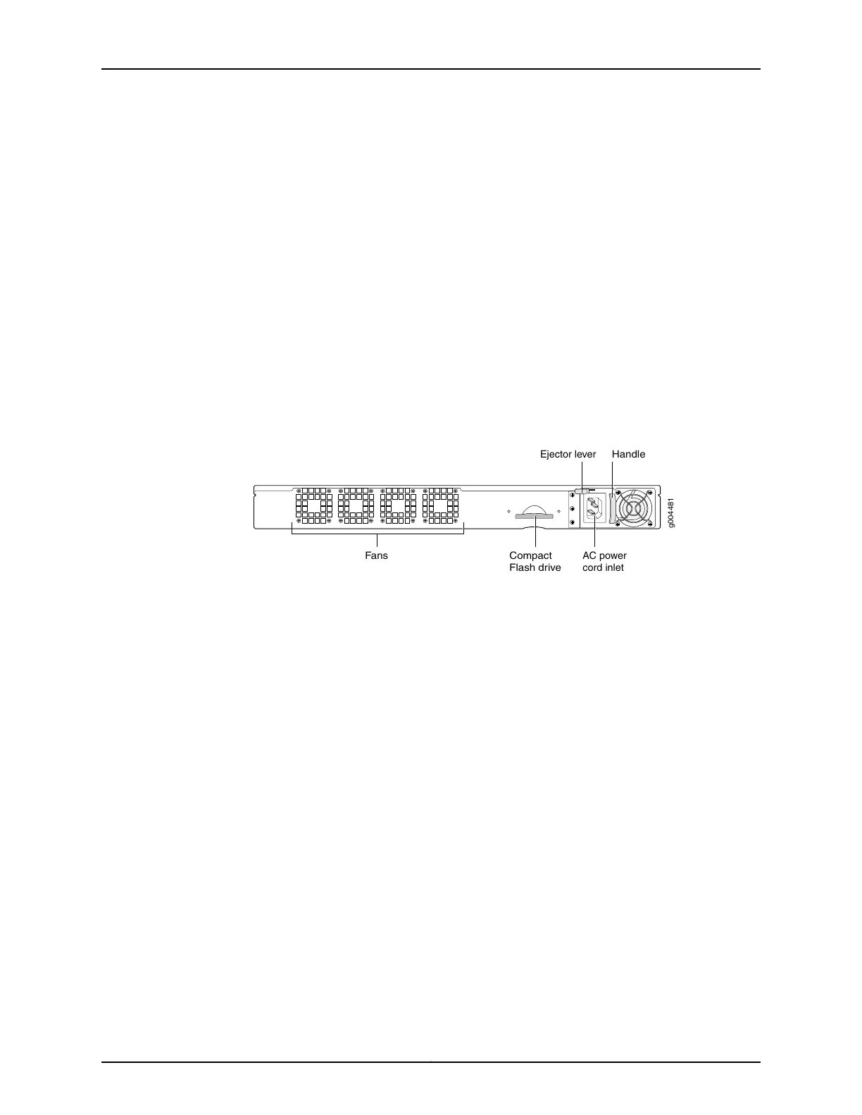
Figure 39: Replacing an AC Power Supply
g004481
Fans Compact
Flash drive
Handle
AC power
cord inlet
Ejector lever
To install an AC power supply (see Figure 39 on page 119):
1. Move the AC input switch next to the appliance inlet on the power supply to the off
(O) position.
2. Using both hands, slide the power supply straight into the chassis until the power
supply is fully seated in the chassis slot. The power supply faceplate should be flush
with any adjacent power supply faceplate or blank installed in the power supply slot.
3. Tighten both captive screws at the bottom of the power supply.
4. Attach the power cord to the power supply.
5. Attach the power cord to the AC power source, and switch on the dedicated customer
site circuit breaker. Follow the instructions for your site.
6. If the chassis has a power switch, move it to the on (|) position.
7. Observe the status LEDs on the power supply faceplate. If the power supply is correctly
installed and functioning normally, the AC OK and DC OK LEDs light steadily, and the
PS FAIL LED is not lit.
Related
Documentation
• Required Tools for Maintaining the CTP Platform on page 117
• Storing CTP Modules and Other Components on page 117
• Cleaning the CTP Platform on page 118
119Copyright © 2017, Juniper Networks, Inc.
Chapter 18: Maintaining Components

 Loading...