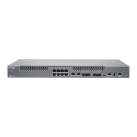
Figure 19: Front Panel of CTP2000 2W-FXS Interface Module
RST
2016
128
40
231915
11
73
CTP2000 IM 2WFXS
Port signaling LEDs
g015381
Figure 20: Rear Panel of CTP2000 2W-FXS RTM
Not used
RJ-21 25-pair connectors
2WFXS RTM
g016231
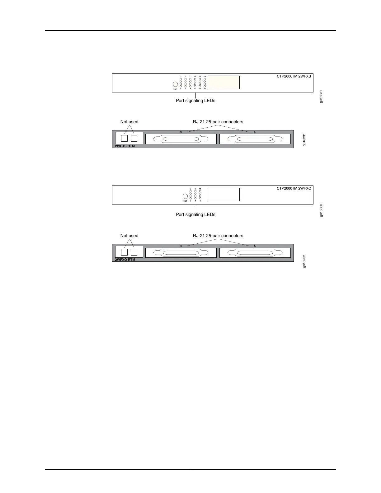
See Figure 21 on page 20 and Figure 22 on page 20 for the CTP2000 2W-FXO interface
module.
Figure 21: Front Panel of CTP2000 2W-FXO Interface Module
Port signaling LEDs
g015380
Figure 22: Rear Panel of CTP2000 2W-FXO RTM
Not used
RJ-21 25-pair connectors
2WFXO RTM
g016232
Both modules use connector A on the RTM. For both modules, connector B and the RJ-45
connectors are not used. See “CTP2000 FXS and FXO Interface Module Cables and
Pinouts” on page 45 for connector pinout information.
You set the signaling by using the software on both modules. You cannot reconfigure the
jumper parameters.
Required Cables and Pinouts
The CTP2000 2W-FXS and 2W-FXO interface modules require the use of double-shielded
cables (copper braid plus aluminum mylar foil) to ensure EMI compliance. See “CTP2000
FXS and FXO Interface Module Cables and Pinouts” on page 45 for particulars about
cable pinouts.
Analog FXS/FXO Loop-Start Signaling
There are two basic signaling protocols for FXS/FXO interfaces: loop-start and
ground-start. Residential telephones use loop-start. Ground-start is typically used
between a CO and a PBX to prevent “glare.” Glare occurs when a call is established by
the FXS device and the FXO device tries to make a call before the ring has been detected.
When a call is initiated from the CO (or FXS) side, the FXS interface puts an AC ring
voltage on the R lead (typically 70-90 Vrms). This ring voltage generates the ringing that
you hear on an analog phone. When the FXO device answers the call (someone picks up
Copyright © 2017, Juniper Networks, Inc.20
CTP2000 Hardware Documentation

 Loading...