3. Locate the power cord or cords shipped with the switch; the cords have plugs
appropriate for your geographical location. See “AC Power Cord Specifications for
EX3200 and EX4200 Switches” on page 102.
WARNING: Ensure that the power cord does not block access to switch components
or drape where people can trip on it.
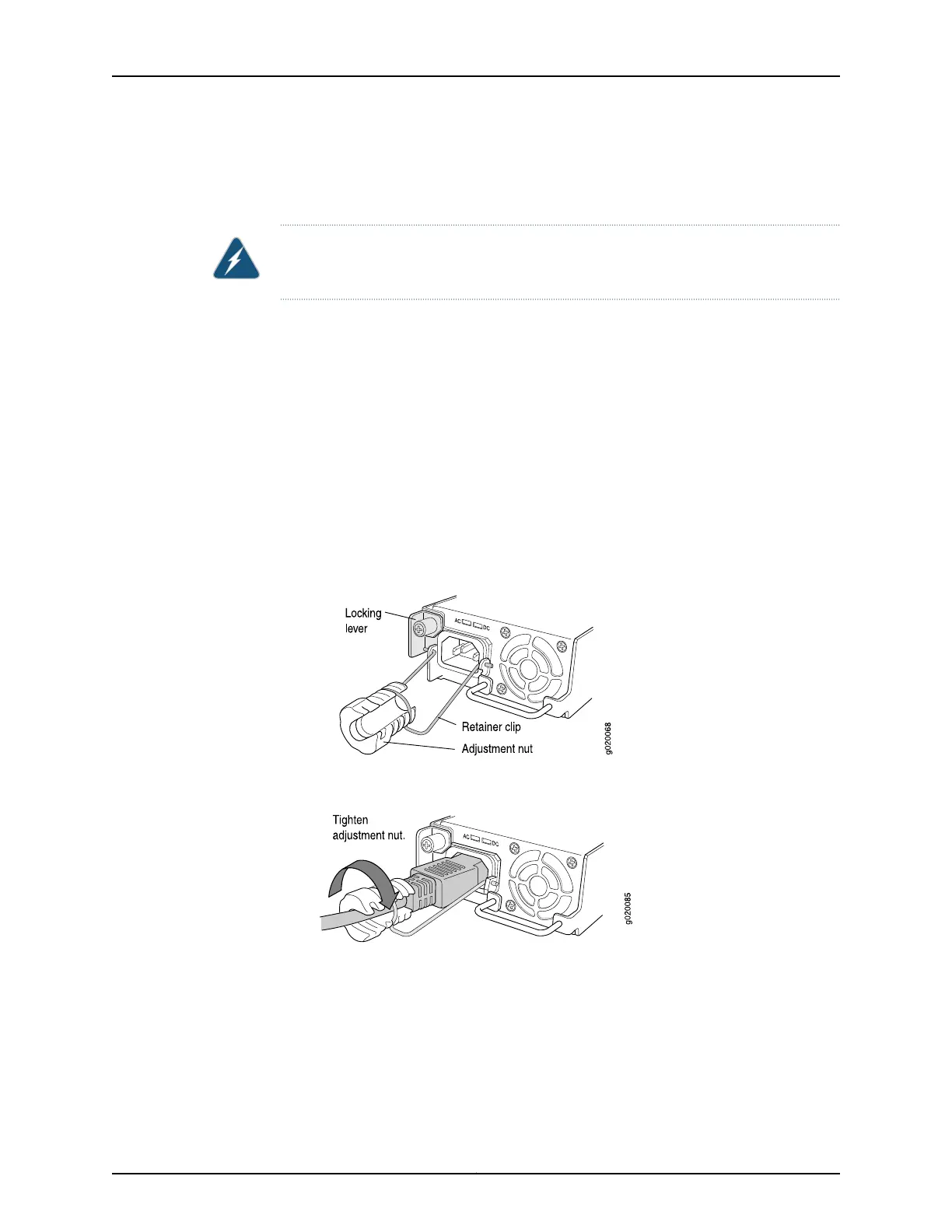
4. Insert the coupler end of the power cord into the AC power cord inlet on the AC power
supply faceplate.
5. Push the cord into the slot in the adjustment nut of the power cord retainer. Turn
the nut until it is tight against the base of the coupler and the slot in the nut is turned
90° from the top of the switch (see Figure 55 on page 148).
6. If the AC power source outlet has a power switch, set it to the OFF (0) position.
7. Insert the power cord plug into an AC power source outlet.
8. If the AC power source outlet has a power switch, set it to the ON (|) position.
9. Verify that the AC OK LED on the power supply is lit and is on steadily.
Figure 54: Connecting the AC Power Cord Retainer Clip to an AC Power
Supply in an EX3200 or EX4200 Switch
Figure 55: Connecting an AC Power Cord to an AC Power Supply in an
EX3200 or EX4200 Switch
Related Topics Connecting and Configuring an EX Series Switch (CLI Procedure) on page 165•
• Connecting and Configuring an EX Series Switch (J-Web Procedure) on page 167
• Connecting DC Power to an EX3200 or EX4200 Switch on page 149
• Power Supply in EX3200 and EX4200 Switches on page 27
• AC Power Supply LEDs in EX3200 and EX4200 Switches on page 30
Copyright © 2010, Juniper Networks, Inc.148
Complete Hardware Guide for EX3200 and EX4200 Ethernet Switches
 Loading...


