•
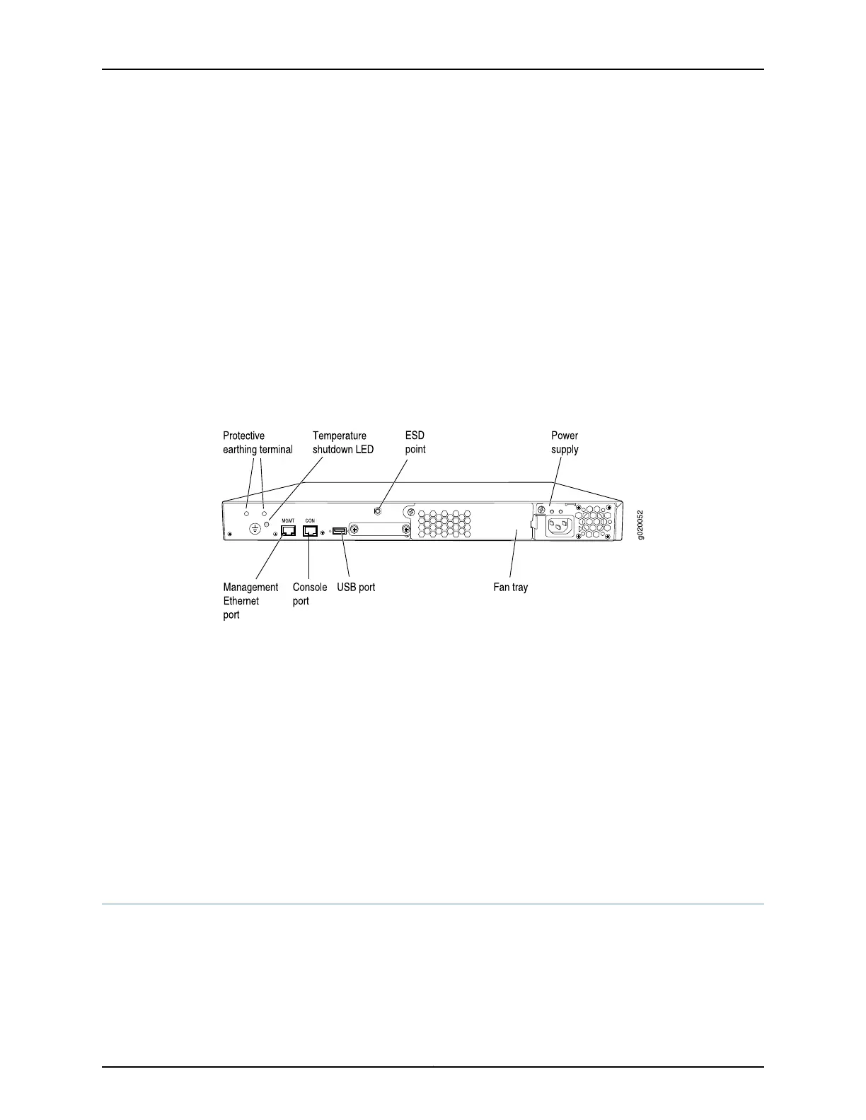
Management Ethernet port
•
Console port
•
USB port
•
ESD point
•
Fan tray
•
Power supply
Figure 3 on page 9 shows the rear panel of an EX3200 switch with a 320 W power
supply. All EX3200 switches have the same rear panel. The 320 W AC power supply and
the 190 W DC power supply are flush with the chassis. The 600 W AC power supply and
930 W AC power supply extend out of the chassis by 2.25 in. The power cord retainer
clips extend out of the power supply by 3 in.
Figure 3: EX3200 Switch Rear Panel
Related Topics Field-Replaceable Units in EX3200 and EX4200 Switches on page 18•
• Front Panel of an EX3200 Switch on page 7
• USB Port Specifications for an EX Series Switch on page 39
• Cooling System and Airflow in an EX3200 Switch on page 31
• Power Supply in EX3200 and EX4200 Switches on page 27
• Prevention of Electrostatic Discharge Damage on EX Series Switches on page 236
• Connecting Earth Ground to an EX Series Switch on page 141
• Installing and Removing EX3200 and EX4200 Switch Hardware Components on
page 131
Front Panel of an EX4200 Switch
The front panel of an EX4200 switch consists of the following components:
•
Network ports—depending on the switch model, either of:
9Copyright © 2010, Juniper Networks, Inc.
Chapter 1: EX3200 and EX4200 Switches Overview
 Loading...


