Standards Supported by These Cables
The cables comply with the following standards:
•
SFP mechanical standard SFF-843—see ftp://ftp.seagate.com/sff/SFF-8431.PDF.
•
Electrical interface standard SFF-8432—see ftp://ftp.seagate.com/sff/SFF-8432.PDF.
•
SFP+ Multi-Source Alliance (MSA) standards
Related Topics Optical Interface Support in EX3200 and EX4200 Switches on page 43•
• Optical Interface Support in EX4500 Switches
• Optical Interface Support in EX8200 Switches
• Installing a Transceiver in an EX Series Switch on page 137
• Removing a Transceiver from an EX Series Switch on page 179
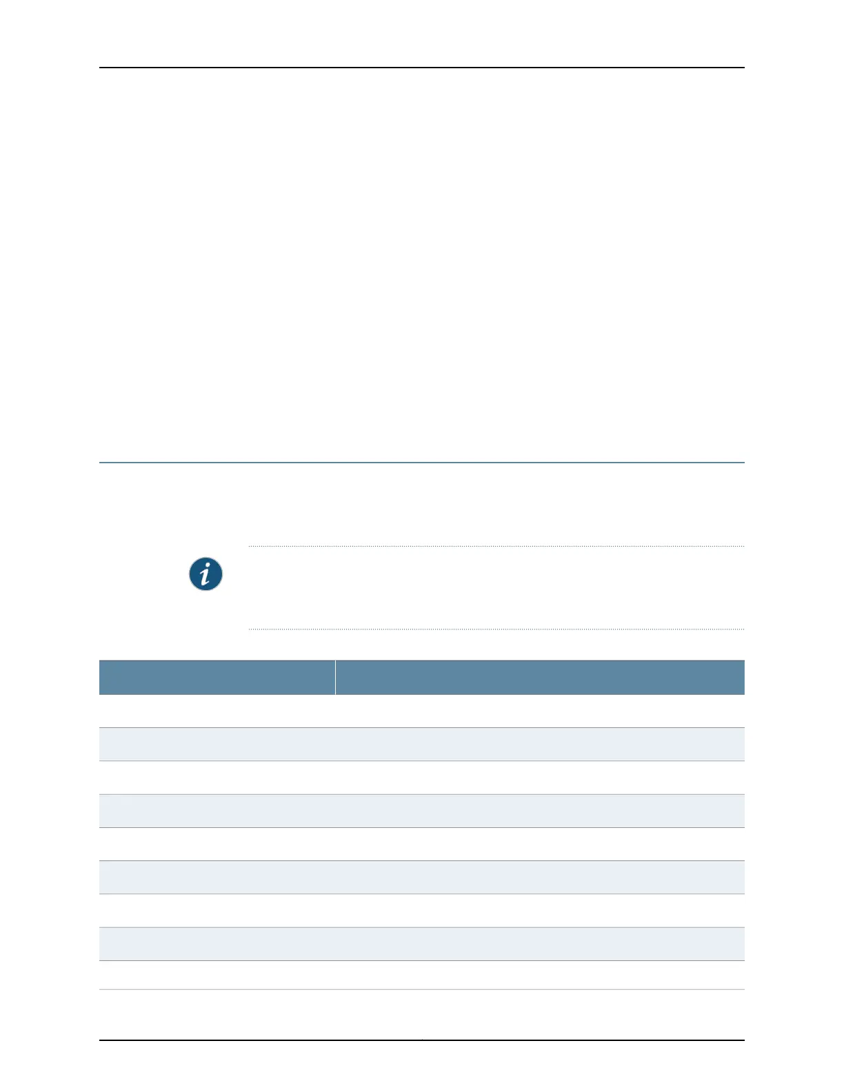
Uplink Modules Connector Pinout Information for EX3200 and EX4200 Switches
EX3200 and EX4200 switches have a field-replaceable unit (FRU) uplink module on the
front panel. Table 23 on page 73 provides the uplink modules connector pinout
information.
NOTE: You can use these ports to connect an access switch to a distribution switch.
You can also use optional uplink module ports to connect members of a Virtual Chassis
across multiple wiring closets.
Table 23: Uplink Modules Connector Pinout Information for EX3200 and EX4200 Switches
Pin NamePin Number
GNDA1
GNDA2
GNDA3
GNDA4
GNDA5
GNDA6
GNDA7
GNDA8
GNDA9
73Copyright © 2010, Juniper Networks, Inc.
Chapter 3: Component Specifications
 Loading...


