2100-900-01 Rev. D / September 2011 Return to Section Topics 2-23
Model 2100 6 1/2-Digit Resolution Digital Multimeter User’s Manual Section 2: Getting Started
Annunciators on the right
• 4W: Indicates 4-wire mode is selected for resistance measurement
• : Indicates that continuity testing is enabled
• : Indicates the diode testing operation was initiated
• EXT: Indicates the External Trigger mode is been enabled
• LOCK: Indicates the front panel menu operation is locked
• OFF: Indicates the front panel display is turned off
Figure 2-33
Annunciators on the right
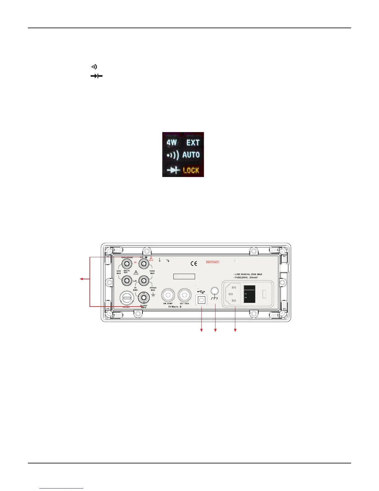
The rear panel
The rear panel of the Model 2100 is shown in Figure 2-34. This figure includes important
abbreviated information that should be reviewed before using the instrument.
Figure 2-34
The rear panel
1. Inserted connections and fuse devices:
a. Input HI and LO: Used for DCV, ACV, O2, CONT, FREQ, PERIOD, and RTD
temperature measurements
AMPS: Used with INPUT LO for DCI and ACI measurements; also
holds current fuse for front panel amps input
SENSE HI and LO: Use with INPUT HI and LO for O4 and RTD temperature
measurements
b. LO and I: Used for making AC and DC current measurements
c. Rear fuse: Secures the meter against damage by strong current pulses
2. USB connection:
a. Connects a remote computer to operate the meter (instead of the front panel control)
3. Chassis ground terminal
4. Power module:
CAT 1000V
CAT 600V
120V
240V
24
0V
*T w0 00 01 00 0*
MADE IN
TA IWA N
NO INTERNA L SERVICEAB LE PARTS, SERVICE
WA RN IN G
BY QUALIFIED PERSONNEL ONLY.
FOR CONTINUED PROTECTION AGAINST FIRE HAZARD.
CAUTION:
REPLACE FUSE WITH SAME TYPE A ND RATING.
1
432

 Loading...


