2100-900-01 Rev. D / September 2011 Return to Section Topics 4-13
Model 2100 6 1/2-Digit Resolution Digital Multimeter User’s Manual Section 4: Front Panel Operations
SENSe:TEMPerature:RTD:TYPE{PT100|D100|F100|PT385|PT3916|USER|SPRTD}
SENSe:UNIT {Cel|Far|K}
SENSe:UNIT?
SENSe:TEMPerature:RTD:RZERo {<value>|MINimum|MAXimum}
SENSe:TEMPerature:RTD:ALPHa {<value>|MINimum|MAXimum}
SENSe:TEMPerature:RTD:BETA {<value>|MINimum|MAXimum}
SENSe:TEMPerature:RTD:DELTa {<value>|MINimum|MAXimum}
SENSe:TEMPerature:SPRTD:RZERo {<value>|MINimum|MAXimum}
SENSe:TEMPerature:SPRTD:A4 {<value>|MINimum|MAXimum}
SENSe:TEMPerature:SPRTD:B4 {<value>|MINimum|MAXimum}
SENSe:TEMPerature:SPRTD:AX {<value>|MINimum|MAXimum}
SENSe:TEMPerature:SPRTD:BX {<value>|MINimum|MAXimum}
SENSe:TEMPerature:SPRTD:CX {<value>|MINimum|MAXimum}
SENSe:TEMPerature:SPRTD:DX {<value>|MINimum|MAXimum}
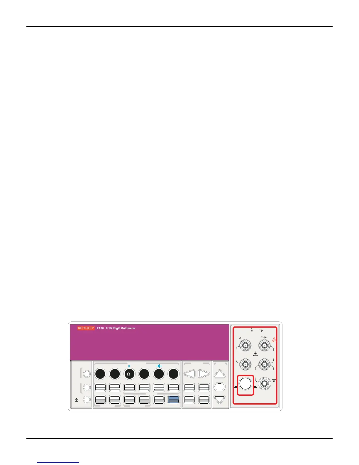
Input terminal switch
Definition
This Model 2100 has five input terminals on both the front and rear terminals for taking
measurements. When the rear input is selected, the REAR annunciator is shown on the front
panel display.
Default
The default setting is the front terminals.
How to switch the terminals:
To switch between the front and rear input terminals, press the INPUTS button on the front panel
(refer to
Figure 4-7 for the location of the button and terminals).
Figure 4-7
Front panel input switch terminals
FILTER
NEXT
PREV
DIGITS
RATIO
%
MIN/MAX
NULL
ESC
ENTER
AUTO
SINGLE
TRIGGER
STORE
RECALL
LOCAL
SHIFT
CONFIG
MENU
AUT O
DCV
ACV
22
FREQ
CONT
TEMP
4 WIRE
RATIO
V
INPUT
PEAK
200V
PEAK
HI
LO
PEAK
500V
3A
RMS
INPUTS
3A 250V
FRONT/REAR
AMPS
R
1000V
REF
CAT 1000V
CAT 600V
LOCK
SETUP
ACV
22
FUNCTION
DCI ACI
4
PERIOD
LIMITS MX+B
dB
EXTRIG
HOLD
MATH
TRIGGER MEMORY
dBm
RANGE
DISPLAY
NEXT
PREV
POWER
OFF
ON
SENSE
F

 Loading...


