5-2 Return to Section Topics 2100-900-01 Rev. D / September 2011
Section 5: Remote Interface Operations Model 2100 6 1/2-Digit Resolution Digital Multimeter User’s Manual
Introduction
The Keithley Instruments Model 2100 6 1/2-Digit Resolution Digital Multimeter has a built-in USB
interface for remote interface operations.
This section provides an overview of some of the SCPI commands (Standard Commands for
Programmable Instruments) available to control the Model 2100. For a more detailed explanation
of SCPI commands, refer to “
Appendix B: Remote Interface Reference.”
Pass/fail output from the USB connector
The USB connector on the rear panel of the Model 2100 is a series "B" connector. When the USB
interface is disabled, the internal pass and fail TTL output signals (limit testing) will be connected
to the USB connector.
The Pass/Fail signals are low true and indicate the Math Pass/Fail Limit Test result for the next
reading to be output.The signals are active low for approximately 2ms (+/-100s) for each reading
taken.
To enable/disable the Pass/Fail output function:
There are two procedures you can use to enable or disable the Pass/Fail output function:
1. Press the MENU key, then use the PREV and NEXT keys to select INTERFACE, and press
ENTER
2. Next, use the left and right arrow keys to select USB, then press ENTER.
3. Use the left and right arrow keys to select ENABLE or DISABLE, then press ENTER.
Procedure: MENU INTERFACE USB ENABLE/DISABLE
or
1. Press the CONFIG+SHIFT+RATIO keys, then use the left and right arrow keys to select
OUTPUT, and press ENTER.
2. Use the left and right arrow keys to select ENABLE or DISABLE, then press ENTER.
Procedure: CONFIG+SHIFT+RATIO OUTPUT ENABLE/DISABLE
NOTE You cannot use the USB interface for remote control if you want to enable the Pass/Fail
signal output. Disconnect the USB cable from your multimeter to eliminate abnormal
output of the Pass/Fail signal.
Setting up the remote interface
You can use KI-TOOL, 2100 Excel Add-in, and 2100 Word Add-in programs developed by Keithley
Instruments to remotely control and configure the Model 2100 multimeter through the USB
interface.
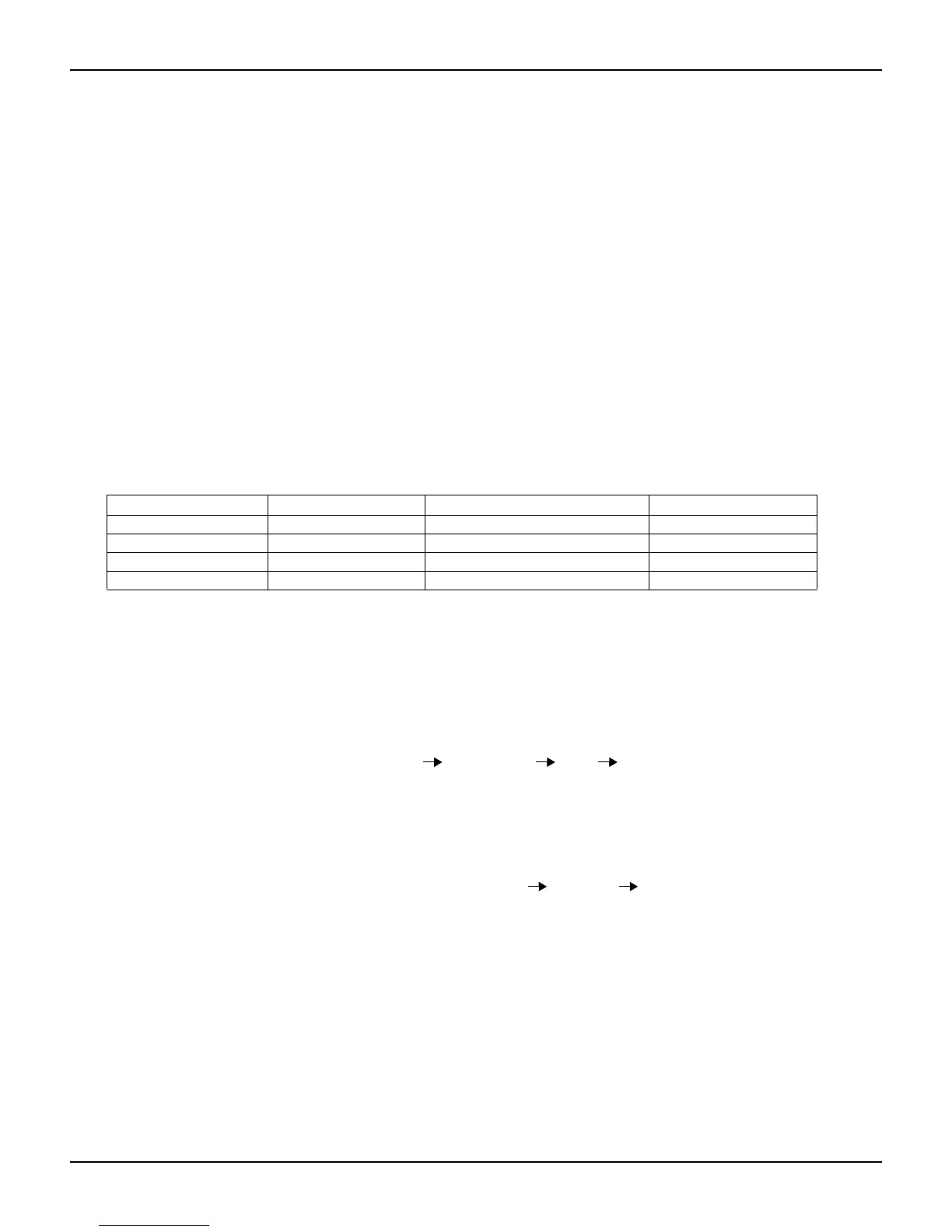
Table 5-1
USB connector pin out and designations
Contact number Signal name Typical wiring assignment Description
1 VBUS Red Floating
2 D- White Limit test pass
3 D+ Green Limit test fail
4 GND Black Ground

 Loading...


