3-10 Return to Section Topics 2100-900-01 Rev. D / September 2011
Section 3: Basic Measurement Functions Model 2100 6 1/2-Digit Resolution Digital Multimeter User’s Manual
c) Using the PREV and NEXT keys, select the SENSOR.
d) Press ENTER.
3. Select USER RTD and press ENTER.
4. Select R-ZERO and press ENTER.
5. Enter in the sum of the zero RTD resistance plus the resistance of the third wire measured
in step two (e.g., 100 Ohms plus 0.05 Ohms = 100.05 Ohms).
6. Also select the ALPHA, BETA, and DELTA parameters, and enter the coefficients for this
particular RTD. The manufacturer of the RTD normally provides these values in the
documentation shipped with the RTD.
7. Use the USER RTD selection as the SENSOR.
4-wire RTD measurements
How to measure temperature with a 4-Wire RTD
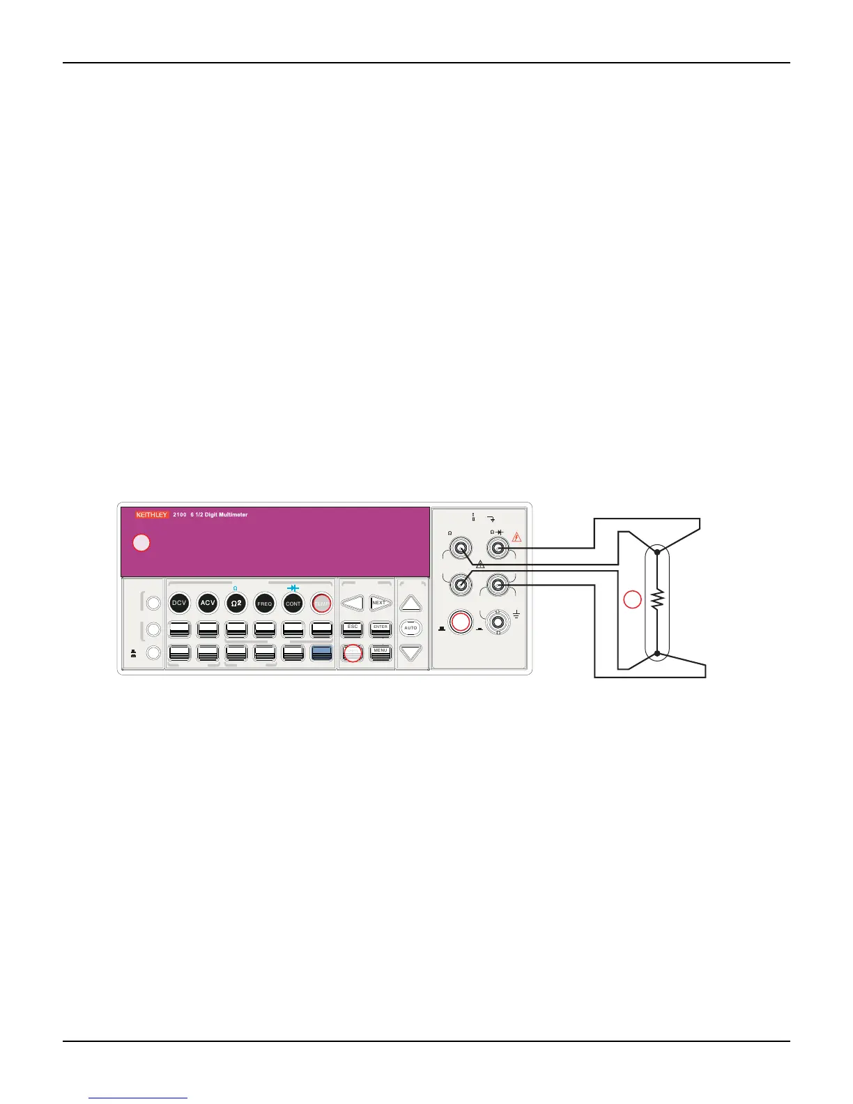
Figure 3-14 shows a theory diagram of a 4-wire RTD measurement:
Figure 3-14
Theory diagram of 4-wire RTD measurement
To measure temperature with a 4-wire RTD:
1. Use the terminals switch to select front terminals.
2. Connect the low thermal leads as shown in Figure 3-14.
3. Configure sensor type and unit using CONFIG + TEMP and the PREV or NEXT keys. When
ready, press the ENTER key.
4. Press the TEMP key.
5. Place the RTD at the measurement point and read the display.
FILTER
NEXT
PREV
DIGITS
RATIO
%
MIN/MAX
NULL
ESC
ENTER
AUTO
SINGLE
TRIGGER
STORE
RECALL
LOCAL
SHIFT
CONFIG
MENU
AUTO
DCV
ACV
22
FREQ
CONT
TEMP
4 WIRE
RATIO
V
INPUT
PEAK
200V
PEAK
HI
LO
PEAK
500V
3A
RMS
INPUTS
3A 250V
FRONT/REAR
AMPS
R
1000V
REF
CAT 1000V
CAT 600V
LOCK
SETUP
ACV
22
FUNCTION
DCI ACI
4
PERIOD
LIMITS MX+B
dB
EXTRIG
HOLD
MATH
TRIGGER MEMORY
dBm
RANGE
DISPLAY
NEXT
PREV
POWER
OFF
ON
SENSE
F
4
5
Platinum
RTD
Sense Ω4-wire HI
Input HI
Input LO
Sense Ω4-wire

 Loading...


