2100-900-01 Rev. D / September 2011 Return to Section Topics 3-7
Model 2100 6 1/2-Digit Resolution Digital Multimeter User’s Manual Section 3: Basic Measurement Functions
6. Connect test leads to your source signal and observe the reading shown on the display. If
the input signal is beyond the allowed range, an overflow message ("OVLD") will be
displayed.
NOTE Follow the same procedure when using either the front or rear panel terminals (refer to
Figure 3-3).
Continuity measurements
The Model 2100 uses 1K range for the continuity measurement. The meter beeps when the test
resistance is less than the threshold resistance. The default threshold resistance is 10 , but you
can set the threshold resistance to anything between 1 and 1K . The resistance value you set
is stored in volatile memory and will be cleared after the meter has been turned off. The source
current for the continuity measurement is 1mA.
WARNING The maximum input voltage allowed is 1000V. Applying excess voltage may
damage the meter and cause unpredictable hazards that may result in
personal injury or death.
How to measure the continuity
Select input signal connections on the front or rear panel.
1. Connect the test leads to the terminals as shown in Figure 3-2.
2. Set the input signal reconnect as shown in Figure 3-10.
3. Set threshold resistance by pressing CONFIG + CONT keys, or skip this step if the default
resistance setting is used. When ready, press the ENTER key.
4. Press the CONT key.
5. The measured value will be shown on the display automatically. The meter will beep when
measured resistance value is lower than threshold value.
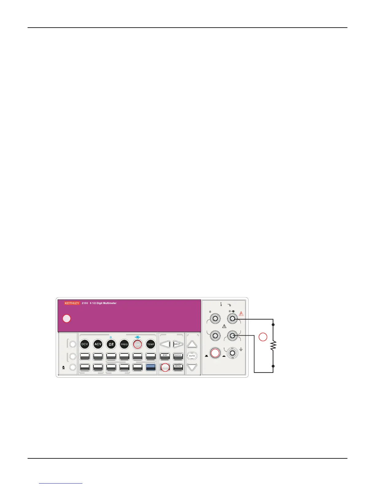
Figure 3-10
Model 2100 2-wire resistance / continuity
Diode measurements
The Model 2100 uses a current source of 1mA for diode testing. The maximum resolution is 10V
on a fixed range of 1VDC. The default threshold voltage is fixed between 0.3V and 0.8V and the
reading rate is fixed at 0.1PLC (the voltage band is adjustable from 0.01V up to 1.2V). The meter
will beep when the diode measured value is in range.
FILTER
NEXT
PREV
DIGITS
RATIO
%
MIN/MAX
NULL
ESC
ENTER
AUTO
SINGLE
TRIGGER
STORE
RECALL
LOCAL
SHIFT
CONFIG
MENU
AUTO
DCV
ACV
22
FREQ
CONT
TEMP
4 WIRE
RATIO
V
INPUT
PEAK
200V
PEAK
HI
LO
PEAK
500V
3A
RMS
INPUTS
3A 250V
FRONT/REAR
AMPS
R
1000V
REF
CAT 1000V
CAT 600V
LOCK
SETUP
ACV
22
FUNCTION
DCI ACI
4
PERIOD
LIMITS MX+B
dB
EXTRIG
HOLD
MATH
TRIGGER MEMORY
dBm
RANGE
DISPLAY
NEXT
PREV
POWER
OFF
ON
SENSE
F
4
5
Ω2 resistance
under test
Note: Source current flows from the INPUT HI to
INPUT LO terminals.