2100-900-01 Rev. D / September 2011 Return to Section Topics 4-5
Model 2100 6 1/2-Digit Resolution Digital Multimeter User’s Manual Section 4: Front Panel Operations
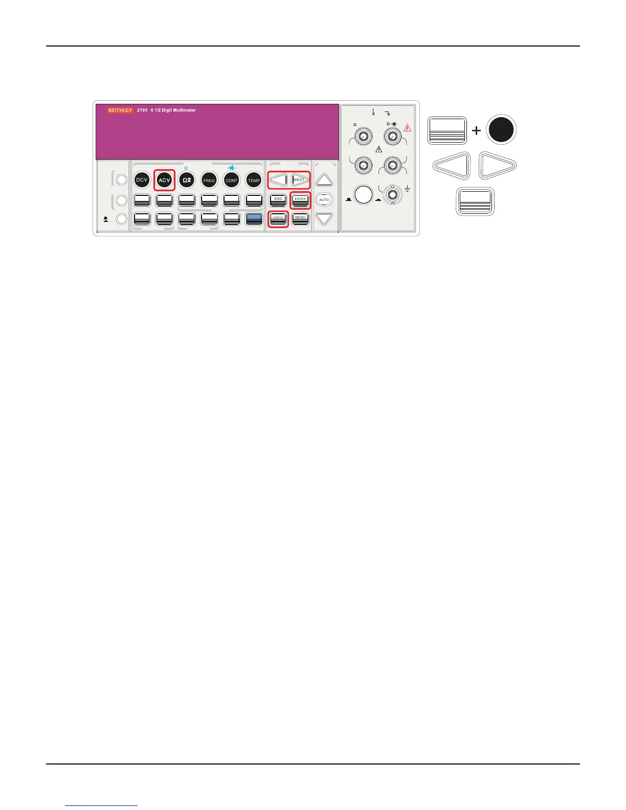
Figure 4-2
Setting the AC Filter using the front panel
Remote interface operation
From your PC terminal, use the following command to specify the filter type:
DETector:BANDwidth_20
Digital filter
Definition
The Model 2100 uses an averaging digital filter to yield a reading from 2 to 100 past measurement
readings (past measurement readings are stored in stack memory). You can select one of two
modes of digital filter operation: Moving Average mode or Repeating Average mode.
The moving average filter puts the specified number of reading conversions in a first-in, first-out
order. The very first measurement reading simply fills up the stack. To yield a reading for display,
the filter produces an average of the stacked measurement readings every time a new
measurement reading is available, replacing the oldest reading in the stack. In the Repeating
Average mode, the multimeter waits for the measurement reading stack to fill up, then take an
average to produce a reading for display. It then flushes the stack and starts over with an empty
stack. Consequently, the repeating digital filter yields one reading for display every specified
number of measurement readings.
The digital filter is not available for diode, continuity, frequency, and period measurements.
Default
The digital filter is enabled, is in Moving Average mode, and is set to use the last 10 readings by
default.
How to enable/disable the digital filter
Press the FILTER key to switch the digital filter function. The FILT annunciator indicates the state
of the digital filter; when it is lit, the filter is enabled.
How to configure the digital filter
You can configure the digital filter through either the front panel operation or the remote interface
operation.
FILTER
NEXT
PREV
DIGITS
RATIO
%
MIN/MAX
NULL
ESC
ENTER
AUTO
SINGLE
TRIGGER
STORE
RECALL
LOCAL
SHIFT
CONFIG
MENU
AUT O
DCV
ACV
22
FREQ
CONT
TEMP
4 WIRE
RATIO
V
INPUT
PEAK
200V
PEAK
HI
LO
PEAK
500V
3A
RMS
INPUTS
3A 250V
FRONT/REAR
AMPS
R
1000V
REF
CAT 1000V
CAT 600V
LOCK
SETUP
ACV
22
FUNCTION
DCI ACI
4
PERIOD
LIMITS MX+B
dB
EXTRIG
HOLD
MATH
TRIGGER MEMORY
dBm
RANGE
DISPLAY
NEXT
PREV
POWER
OFF
ON
SENSE
F
NEXT
PREV
ENTER
ACVACV
CONFIG

 Loading...


