Start-up
28
Pos: 12.28 /Übersc hriften/Überschri ften 2/A-E/AAnbau und Ein stellung der Entlastun gsfedern ÜS @ 89\mod_13219 58243040_78.docx @ 75679 7 @ 2 @ 1
5.6 Mounting and Adjusting the Relief Springs
Pos: 12.29 /BA/Sic herheit/7. Gefahrenhin weise alt/Mähwerke/ Gefahr - Einstellung an de n Entlastungsfeder n @ 0\mod_1196751594562_7 8.docx @ 12575 @ @ 1
Danger! - Setting on the compensation springs
Effect: Danger to life or serious injuries
• The compensation springs must only be removed in transport position. In the working
position the compensation springs are subject to high tensile stress.
• Severe injury can be caused if the compensation springs are removed while in the working
position.
• The lower threaded blocks on the compensation springs must be fully screwed in.
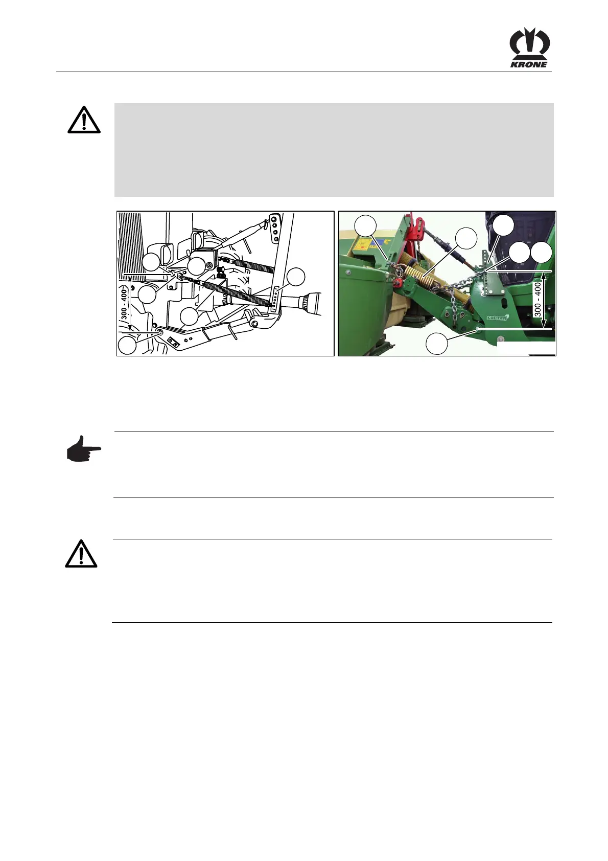
Pos: 12.30 /BA/Einste llungen/Mähwerke/Ea syCut/Entlastung sfeder(n)/Entl astungsfedern am Trakt or einstellen Bild EC F 280/ 320/360 @ 136\mod_135287 8872691_78.docx @ 1211 577 @ @ 1
AFA-1-007
4
3
1
2
a
5
EC-443-0
4
3
a
2 1
5
Fig. 13
Pos: 12.31 /BA/Einste llungen/Mähwerke/Ea syCut/Entlas tungsfeder(n)/Entl astungsfedern am Trakt or einstellen Text EC 28/32 2 8/32 CV @ 10\mod_1221737 190442_78.docx @ 136798 @ @ 1
• Bring the front mowing unit into the transport position
• Hook compensation spring (3) onto perforated bar (4).
• Attach with holder (2) on support point "a" and secure with hinged cotter pin (1)
Pos: 12.32 /BA/Einste llungen/Mähwerke/Ea syCut/Entlastung sfeder(n)/Ei nstellen der Entlastungsf edern am Traktor Maß 300-40 0 Hinweis @ 10\mod_1221737 438036_78.doc x @ 136841 @ @ 1
Note
Setting dimension of the compensation springs
Effect: Proper use of the machine.
The distance between support point "a" of the compensation spring (3) and the pivot point of
the tractor's lower suspension arms (5) should be between 300 – 400 mm.
Pos: 12.33 /BA/Inbetr iebnahme/EasyCut/Pr obelauf nach Erstmo ntage @ 3\mod_120521592 7275_78.docx @ 73555 @ 2 @ 1
5.7 Trial run after first installation
Caution!
After the first connection to the tractor, the machine must undergo a trial run.
• The machine must be in working position
• Do not switch on the PTO until the machine is resting on the ground and you are absolutely
sure that there are no persons, animals or objects in the danger zone.
• Start a trial run of the machine from the driver’s seat of the tractor only.
• Lower the machine into working position.
• Carefully switch in the PTO of the tractor.
• Slowly increase the PTO speed to 1000 rpm.
• Check that the machine is running smoothly and without vibrations.
• Reduce the PTO speed to idling and wait for the cutting discs / mower drums to come to a
stansdstill.
• Raise or lower the machine via the tractor hydraulics.
Pos: 12.34 /Layout Module /---------------Seitenumbruch---------------- @ 0\mod_1196175311226_0. docx @ 4165 @ @ 1
 Loading...